Because of the holidays, TI E2E™ design support forum responses will be delayed from Dec. 25 through Jan. 2. Thank you for your patience.

This thread has been locked.

If you have a related question, please click the "Ask a related question" button in the top right corner. The newly created question will be automatically linked to this question.

TMS320F28379D: Adding RS232 and RS485 to other SCIs

Part Number: TMS320F28379D
Other Parts Discussed in Thread: TMDSDOCK28379D, CONTROLSUITE, TMDSCNCD28379D

Hi,

currently, I am using USB to connect to TMDSDOCK28379D and TMDSDOCK28379D and control the external high-frequency converter. More than often communication breaks down when the converter voltage and power increase when I am in the MATLAB Simulink External Mode for Parameter Tuning and Signal Logging with Serial Communication.

I was thinking of adding RS232 and RS485 communication to load applications and monitor data. Maybe this will make the communication more robust?!

There are four SCIs (SCI_A, SCI_B, SCI_C and SCI_D) in Simulink settings and I can assign various GPIOs from the list to RX and TX.

1. How the system knows which SCI is used? There is an option 'Pin Assignment: None' in the settings for each SCI RX/TX; is this the only way to turn off the each channel SCI communication? Can I have more communications channels on 'stand-by' so I can try them all while the system is running? I would like to use other SCIs, e.g., SCI_B for RS232 and SCI_C for RS485, but not sure how the system will know which one is active

2. I have created a basic schematics for RS232 and RS485. Will this work or do I need to add something?
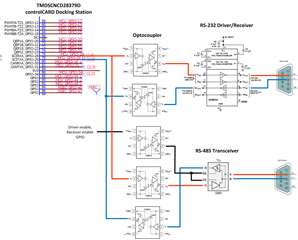
Thank you in advance

  • Hi Mike,

    Thank you for reaching out. Someone from the Mathworks team will respond to your questions soon.

    Best Regards,

    Marlyn

  • Hi Mike,

    Even though the SCI modules (SCI_A, SCI_B, SCI_C or SCI_D) are configured under configuration parameters under hardware implementation pane, unless the respective SCI block is added in the model, you may not be able to use these modules as the SCI registers are not initialized in the generated code.

    If you need to have these channels on 'stand-by', you need to add the blocks and configure the respective module in the model. As an alternative, you can also use system initialize block and add the custom code to configure the required registers.

    Best Regards,
    Ram Alla.

  • Hi Ram Alla,

    thank you for the reply.

    I have to admit I have never used SCI blocks in the MATLAB Simulink... and there was no warning saying I need it. I see in the F28379D schematic that GPIO-28 and GPIO-29 go to Isolator, FTDI's USB chip and USB-B connector. For loading and tuning, I plug in a USB cable, no special block in the code, just make sure GPIOs for SCI_A are set to 28 and 29.

    In Simulink Model Configuration Parameters -> Hardware Implementation -> Target hardware resources I see SCI_A, SCI_B, SCI_C or SCI_D for which I can assign any of the available GPIOS from the drop-down list.

    My question is: Can I, for example, just connect GPIO-54 and GPIO-55 for SCI_B (and set corresponding GPIOs in Target hardware resources) to optocouplers and RS232 driver from the schematics in my first message and will it work for loading and tuning? Will I be able to have those two channels "active" and one time use USB and another RS232.I am not familiar with any register modifications or adding custom code, hence Simulink, and not CCS :)

  • Hi Mike,

    It is not allowed to configure multiple channels and switch dynamically while running the model in external mode for parameter logging and tuning. 

    Regards,
    Ram Alla.

  • Hi Ram Alla,

    If I understood this correctly, I can use only SCI_A? I was never thinking of switching dynamically between USB, RS232 and RS485.

    My idea was to have USB, RS232 and RS485 options on the board so if the USB link starts breaking because of the noise or EMC, I can use RS485 and still do parameter logging and tuning.

    If this means switching A:SW1 Pos 2 to OFF on F2837x controlCARD (electrical diagram available in C:\TI\controlSUITE\development_kits\~controlCARDs\TMDSCNCD28379D_v1_0\R1_3)

    Pos 2 ON: GPIO28 will be controlled by the USB-to-UART adapter on the FTDI chip
    Pos 2 OFF: GPIO-28 can be controlled by a pin in HSEC connector

    Can I connect then GPIO-28 and GPIO-29 to optocouplers and RS232 driver from the schematics in my first message? Will this give me RS232 communcation?

  • Hi Mike,

    Can I connect then GPIO-28 and GPIO-29 to optocouplers and RS232 driver from the schematics in my first message? Will this give me RS232 communcation?

    This is not something I have tried before so you will need to verify on your own system if this implementation will work or not. Not sure if our device will have the correct drive strength for driving both of the TX lines since you plan on having both the options connected to the device. You also need to ensure the optocouplers/transceivers are not going to have issues being driven in parallel. What might help is implementing another switch in order to choose the RS232 or RS485 path along with the A:SW1 switch. 

    Best Regards,

    Marlyn

  • Hi Mike,

    Instead of external mode, you may also consider to use Two-model approach as it allows higher baud rates.

    Refer to the below FAQ for more details on Two model approach:

    How can I use a two model approach in MathWorks Embedded Coder for signal logging and parameter tuning on a TI C2000?

    Best Regards,

    Ram Alla.