


Hello, I am trying to generate PWM signals in the range of ~100kHz frequency using TI's control card F28379D. I want to generate these signals on PWM channels 1A,1B,2A,2B,5A,5B,6A and 6B. I am using the epwm_deadband example code with slight modifications for this.
I want a small dead time between the A and B signals (A and B are supposed to be complementary signals) of each PWM channel. I observe that PWM signals 5A,5B,6A and 6B come out to be fine with the programmed dead time between them. However, signals 1B and 2B are inconsistent, with their duty cycles varying in each time period and there is no dead time between signals 1A and 1B; and between signals 2A and 2B.
.The Interrupt subroutine and epwm_function for PWM channel1 in my code is given below: (similar code is used for the other channels)
__interrupt void epwm1_isr(void)
{
if(EPwm1_DB_Direction == DB_UP)
{
if(EPwm1Regs.DBFED.all < EPWM1_MAX_DB)
{
EPwm1Regs.DBFED.all++;
EPwm1Regs.DBRED.all++;
}
else
{
EPwm1_DB_Direction = DB_DOWN;
EPwm1Regs.DBFED.all--;
EPwm1Regs.DBRED.all--;
}
}
else
{
if(EPwm1Regs.DBFED.all == EPWM1_MIN_DB)
{
EPwm1_DB_Direction = DB_UP;
EPwm1Regs.DBFED.all++;
EPwm1Regs.DBRED.all++;
}
else
{
EPwm1Regs.DBFED.all--;
EPwm1Regs.DBRED.all--;
}
}
EPwm1TimerIntCount++;
// Clear INT flag for this timer
EPwm1Regs.ETCLR.bit.INT = 1;
// Acknowledge this interrupt to receive more interrupts from group 3
PieCtrlRegs.PIEACK.all = PIEACK_GROUP3;
}
void InitEPwm1Example()
{
EPwm1Regs.TBPRD = 100; // Set timer period
EPwm1Regs.TBPHS.bit.TBPHS = 0x0000; // Phase is 0
EPwm1Regs.TBCTR = 0x0000; // Clear counter
// Setup TBCLK
EPwm1Regs.TBCTL.bit.CTRMODE = TB_COUNT_UPDOWN; // Count up
EPwm1Regs.TBCTL.bit.PHSEN = TB_DISABLE; // Disable phase loading
EPwm1Regs.TBCTL.bit.HSPCLKDIV = TB_DIV4; // Clock ratio to SYSCLKOUT
EPwm1Regs.TBCTL.bit.CLKDIV = TB_DIV4; // Slow so we can observe on
// the scope
// Setup compare
EPwm1Regs.CMPA.bit.CMPA = 50;
//EPwm1Regs.CMPB.bit.CMPB = 60;
// Set actions
EPwm1Regs.AQCTLA.bit.CAU = AQ_SET; // Set PWM3A on Zero
EPwm1Regs.AQCTLA.bit.CAD = AQ_CLEAR;
EPwm1Regs.AQCTLB.bit.CAU = AQ_CLEAR; // Set PWM3A on Zero
EPwm1Regs.AQCTLB.bit.CAD = AQ_SET;
// Active high complementary PWMs - Setup the deadband
EPwm1Regs.DBCTL.bit.OUT_MODE = DB_FULL_ENABLE;
EPwm1Regs.DBCTL.bit.POLSEL = DB_ACTV_HIC;
EPwm1Regs.DBCTL.bit.IN_MODE = DBA_ALL;
EPwm1Regs.DBRED.all = 5;
EPwm1Regs.DBFED.all = 5;
EPwm1_DB_Direction = DB_UP;
// Interrupt where we will change the deadband
EPwm1Regs.ETSEL.bit.INTSEL = ET_CTR_ZERO; // Select INT on Zero event
EPwm1Regs.ETSEL.bit.INTEN = 1; // Enable INT
EPwm1Regs.ETPS.bit.INTPRD = ET_3RD; // Generate INT on 3rd event
}
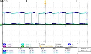
PWM waveforms generated from PWM channel1 (1A - light blue, 1B - dark blue) is attached. It can be seen that duty ratio of 1B varies in consecutive time periods (It is programmed to be 50%). Also, there is no dead-time between 1A and 1B.
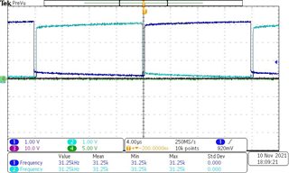
PWM waveforms generated from PWM channel5 (5A - light blue, 5B - dark blue) is attached here. The duty ratios are consistent and there is a dead time between 5A and 5B (as expected).
I tried commenting out the following section of the InitEPwm1Example() function:
// Active high complementary PWMs - Setup the deadband
EPwm1Regs.DBCTL.bit.OUT_MODE = DB_FULL_ENABLE;
EPwm1Regs.DBCTL.bit.POLSEL = DB_ACTV_HIC;
EPwm1Regs.DBCTL.bit.IN_MODE = DBA_ALL;
EPwm1Regs.DBRED.all = 5;
EPwm1Regs.DBFED.all = 5;
EPwm1_DB_Direction = DB_UP;
// Interrupt where we will change the deadband
EPwm1Regs.ETSEL.bit.INTSEL = ET_CTR_ZERO; // Select INT on Zero event
EPwm1Regs.ETSEL.bit.INTEN = 1; // Enable INT
EPwm1Regs.ETPS.bit.INTPRD = ET_3RD; // Generate INT on 3rd event
and observed that signals 1B and 2B are now fine (they have consistent duty ratio for all the time period). however, commenting this section out means that I no longer have a dead time between signals A and B.
I would really appreciate if someone could look into this for me and suggest me a way to fix this issue?