This thread has been locked.

If you have a related question, please click the "Ask a related question" button in the top right corner. The newly created question will be automatically linked to this question.

TMS320F280049: CAN transmitting data losing

Part Number: TMS320F280049
Other Parts Discussed in Thread: SN74LVC1G11, C2000WARE

Hello:

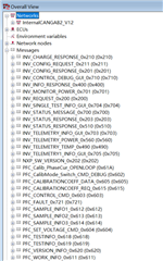
I encountered a problem when  I configure the CAN peripheral of F280049 :There are three nodes in the CAN bus as you can see in the picture,the CAN IDs transmitted by the F280049 are beginning with 0x61_ and the transmitting cycle is 100ms,the problem is when I monitor the communication data of the bus I find that the 0x61_ frames are easy to disappear about  seconds!And I have found that when I transmitting a large number of  0x203 data frame to the bus(about 50 times per 20ms) with my computer is very easy to cause the losing of 0x61_data frame and when I transmit 0x701 would not case the losing. Now my confusion is why the 0x61_ data frames transmitted by the F280049 lost in the bus? Is because the bus arbitration,bus disturbance or others?How can I solve this problem?
  • I. Maybe the following tests can help:

    1. Using the USBCAN monitoring bus, it was found that the maximum loss could be 11s(send cycle is 100ms) 

    2. Using USBCAN to quickly send data frame 0x203 to the bus will easily trigger F28009 frame loss

    3. Erase the programs of the other two nodes on the bus, and only keep F280049 . F280049 does not lose frames.

    4. If only CAN module and Timer1 timer module are reserved in F280049's program, frames will still be lost.

    5. Change the ID of one of the frames sent by F280049 to 0x199 (at present, the minimum frame ID on the CAN bus in is 0x201, F280049's IDs all start with 6), use USBCAN to send 0x203 to the bus, and no frame loss of 0x199 occurs.

    6. Disable auto-bus-on function, and use USBCAN to send a large amount of 0x203 bus without losing frames. However, in this case, if an abnormal node of 800kbps baud rate is added to the Bus to make the Bus die, the Bus cannot restart automatically after removing the abnormal node.

    7. Enable the automatic retransmission function of F280049 could reduce frame loss, but can not completely avoid it.

    II. According to the above phenomenon, the following factors are suspected to affect the stability of CAN transmission of F280049:

    1, bus arbitration, it is possible that the data sent by F280049 is crowded by the high priority data frame

    2. Initial initialization of auto-bus-ON function

    3. Initialization of the automatic retransmission function

    4. The influence of other interrupts in the program on CAN interrupts is only a conjecture at present and has not been confirmed

  • Hi,

    Loss of data can be a combination of several factors:

    First, ensure that bus is free of noise/glitches and follow the recommended bus termination of ~120ohms to minimize reflection and ringing. Suggest to capture several CAN frames in the bus through an oscilloscope that has the ability to trigger with CAN frames, this way you can see whether data is transmitting correctly in the CAN bus. For the node that seems to be losing data, you can monitor CAN_ES register to see what errors are reported (example: is TxOk flag set or not?  and what is the value of LEC and is bus in off state or is there a parity error reported...etc)  You can refer to the following app notes for basics of CAN bus and typical issues encountered as well as the different CAN errors introduced on the frame:

    http://www.ti.com/lit/sprace5

    http://www.ti.com/lit/spracq3

    Second, ensure that the CAN bus is not overloaded.  The recommended bus loading should not exceed 30%.  To calculate loading, determine the CAN frame length.  This is just the (1/buadrate) * frame length (typical length of CAN frame for STD ID is ~125 while EXT ID is ~150) divided by the period at which the CAN frames are set.  Example: for node 0x203 and assuming 500kbps, bus loading will be ((1/500kbps)*125*50 frames)/20ms = 62.5% - so in this case node 0x203 is sending too much data.  You can ease the bus load by sending less number of messages or increase the period at which the messages are sent, for instance instead of every 20ms, send it every 60ms.  Check the loading on the other two nodes as well.

    I recommend to first investigate on the first two items I pointed above before we go to the other items you pointed out.

    Regards,

    Joseph 

  • Thanks for help.The bus  termination is 138ohms.And I monitored the CAN_ES register and found that the error code is 4 or 5, also I have monitored the bus loading is about 3% when normal use.
    Besides,I improved the configuration of CAN initialization and enabled the automatic retransmission and then the data loss  disappeared when I use USBCAN to send 0x203 to the bus  increasing the bus loaing to about 60%! But I cann't sure whether it can solve my problem completely.And I also have a confusion that whether It can casuse the data loss because of bus arbitration even the bus loading is lower to 3%.
  • Based from what you described, I think loss of data is happening because the receiving nodes are not fast enough to receive the frame and issue an acknowledgement back.  From my understanding on your setup, there are three CAN nodes which are from F280049 with IDs 0x61, 0x203 and 0x701. 

       - Are all 3 F280049 CAN nodes just sending/transmitting data and only the USBCAN is receiving all the data from the CAN bus?

       - Is there a configuration in your USBCAN to issue an ACK signal upon reception of a message?  I think most of the CAN analyzers have this feature of just listening (no ACK bit sent) and if this is the case the transmitting node will try to keep sending same frame over and over again and would prevent other nodes from sending data so it would be good to turn on the ACK signal on the USBCAN.

       - When the USBCAN receives a message, are there any further actions taken before it starts to receive messages again (maybe it interacts with a PC and waits for it to process the received data)?

    Just trying to see if there are any scenarios above that would prevent the receiving node from capturing all the valid CAN frames in the bus.  In theory, the CAN bus can be 100% loaded but each sent frame should be received and acknowledged as fast as possible to allow the node with the next priority ID to resume its transmission.  Regardless of bus loading, you should ensure that all frames sent are received and acknowledged in a timely manner to ensure that all nodes in arbitration queue have a chance to proceed with their transmission.

    Regards,

    Joseph

  • The three nodes in the bus are from F280049、F28069 and SPC5748G.  As the CANID assignment of this three node,you can see the picture I sent to you in the very begging,the IDs start with 0x6_ are from F280049,the IDs start with 0x5_、 0x7_、0x4_ are from F28069 and the IDs start with 0x2_ are from SPC5748G. The USBCAN is just a tool that  I used to listen and test the bus after our product was found the data loss problem ,it help me with  receiving and displaying  all data on the PC and have no other further action.Because the repetitionrate  of data loss problem is very low in the normal use,so I  also use the USBCAN to send lots of 0x203 frame to the bus to recurrent the problem.How can I confirm the question " all frames sent are received and acknowledged in a timely manner to ensure that all nodes in arbitration queue have a chance to proceed with their transmission" in the case of low repetition rate of data loss problem? Use the oscilloscope?

  • Unfortunately, the picture you are referring to did not make it in the post so i have a hard time understanding your set up.  Can you attach it again?  Are the three nodes only transmitting data?

    Thanks,

    Joseph

  • The picture just contains the IDs in the bus,I list it directly:

    F280049->0x611~0x620;

    F28069->0x710/0x701/0x704/0x700/0x703/0x700/0x400/0x490/0x510/0x560;

    SPC5748->0x210/0x211/0x201/0x203.

    The three nodes are used as power controller and system controller in addition to transmitting data. I will post the CAN Initialization function of F280049 .(This CAN Initialization doesn't enable automatic retransmission  function )

    void CanService_CANBInit(void)
    {
        struct CAN_REGS CanbShadow;
    
        EALLOW;
        /*CAN-B GPIO12 RXD ,GPIO13 TXD*/
       GpioCtrlRegs.GPAPUD.bit.GPIO12   = 0;         // Disable pullup on GPIO12
       GpioCtrlRegs.GPAGMUX1.bit.GPIO12 = 0;        // GPIO12 = CANTXB
       GpioCtrlRegs.GPAMUX1.bit.GPIO12  = 2;        // GPIO12 = CANTXB
    
       GpioCtrlRegs.GPAPUD.bit.GPIO13   = 0;         // Disable pullup on GPIO13
       GpioCtrlRegs.GPAGMUX1.bit.GPIO13 = 0;         // GPIO13 = CANRXB
       GpioCtrlRegs.GPAMUX1.bit.GPIO13  = 2;        // GPIO13 = CANRXB
       GpioCtrlRegs.GPAQSEL1.bit.GPIO13 = 3;        // Asynch input
    
        EDIS;
        //
    
            CanbShadow.CAN_CTL.all = CanbRegs.CAN_CTL.all;
            CanbShadow.CAN_CTL.all = 0x0;//
            CanbShadow.CAN_CTL.bit.Init = 0x1;//Initialization & 0101 Parity function disabled
            CanbShadow.CAN_CTL.bit.PMD = 0x5;///0101
            CanbRegs.CAN_CTL.all = CanbShadow.CAN_CTL.all;
    
            //CanbShadow.CAN_RAM_INIT.all = CanbRegs.CAN_RAM_INIT.all;
            CanbShadow.CAN_RAM_INIT.all = 0x1A;
            CanbRegs.CAN_RAM_INIT.all = CanbShadow.CAN_RAM_INIT.all;
    
            while(!((CanbShadow.CAN_RAM_INIT.all) & CAN_RAM_INIT_MASK == (CAN_RAM_INIT_RAM_INIT_DONE) | (CAN_RAM_INIT_KEY2) | (CAN_RAM_INIT_KEY0)))         /*这一段程序有歧义*/
            {
                // Wait until RAM Init is complete
            }
    
            EALLOW;
            CanbShadow.CAN_CTL.all = CanbRegs.CAN_CTL.all;
            CanbShadow.CAN_CTL.bit.SWR = 0x1;
            CanbRegs.CAN_CTL.all = CanbShadow.CAN_CTL.all;
            DELAY_US(2.0);
    
            CanbShadow.CAN_CTL.all = CanbRegs.CAN_CTL.all;
            CanbShadow.CAN_CTL.bit.ABO = 0x1;
            CanbShadow.CAN_CTL.bit.DAR = 0x1;
            CanbRegs.CAN_CTL.all = CanbShadow.CAN_CTL.all;
    
            CanbShadow.CAN_ABOTR = 0xFF;
            CanbRegs.CAN_ABOTR = CanbShadow.CAN_ABOTR;
            EDIS;
    
            // Delay for 14 cycles
            DELAY_US(2.0);
            // Enable write access to the configuration registers
            CanbShadow.CAN_CTL.all = CanbRegs.CAN_CTL.all;
            CanbShadow.CAN_CTL.bit.CCE = 0x1;
            CanbRegs.CAN_CTL.all = CanbShadow.CAN_CTL.all;
    
            // To set the bit timing register, the controller must be placed in init
            // mode (if not already), and also configuration change bit enabled.
            // State of the init bit should be saved so it can be restored at the end.
            CanbShadow.CAN_CTL.all = CanbRegs.CAN_CTL.all;
            CanbShadow.CAN_CTL.bit.Init = 0x1;
            CanbShadow.CAN_CTL.bit.CCE = 0x1;
            CanbRegs.CAN_CTL.all = CanbShadow.CAN_CTL.all;
    
            ///Configue for 500Kbps
            CanbShadow.CAN_BTR.all = CanbRegs.CAN_BTR.all;
            CanbShadow.CAN_BTR.bit.BRPE = 0x0;
            CanbShadow.CAN_BTR.bit.BRP = 0x9;
            CanbShadow.CAN_BTR.bit.TSEG1 = 0xA;
            CanbShadow.CAN_BTR.bit.TSEG2 = 0x7;
            CanbShadow.CAN_BTR.bit.SJW = 0x3;
            CanbRegs.CAN_BTR.all = CanbShadow.CAN_BTR.all;
    
            CanbShadow.CAN_CTL.all = CanbRegs.CAN_CTL.all;
            CanbShadow.CAN_CTL.bit.CCE = 0x0;
    
            // If Init was not set before, then clear it.
            if(CanbRegs.CAN_CTL.bit.Init == 0x1u)
            {
                CanbShadow.CAN_CTL.bit.Init = 0x0;
            }
            CanbRegs.CAN_CTL.all = CanbShadow.CAN_CTL.all;
    
            CanbShadow.CAN_CTL.all = CanbRegs.CAN_CTL.all;
            CanbShadow.CAN_CTL.bit.IE0 = 0x1;//
        //  CanbShadow.CAN_CTL.bit.EIE = 0x1;
        //  CanbShadow.CAN_CTL.bit.SIE = 0x1;
            CanbRegs.CAN_CTL.all = CanbShadow.CAN_CTL.all;
    
            CanbShadow.CAN_GLB_INT_EN.all = CanbRegs.CAN_GLB_INT_EN.all;
            CanbShadow.CAN_GLB_INT_EN.bit.GLBINT0_EN = 0x1;//
            CanbRegs.CAN_GLB_INT_EN.all = CanbShadow.CAN_GLB_INT_EN.all;
    
            DELAY_US(10.0);
    
    /***************************************************************************
     *  配置CAN发送接收邮箱
    ***************************************************************************/
            CanbMailBoxConfigure(CANMsgOB_WORK_INFO,CANMsgID_WORK_INFO,BitCANTxEnable,FrameStandrad);
            DELAY_US(10.0);
    
            CanbMailBoxConfigure(CANMsgOB_SAMPLE_INFO1,CANMsgID_SAMPLE_INFO1,BitCANTxEnable,FrameStandrad);
            DELAY_US(10.0);
    
            CanbMailBoxConfigure(CANMsgOB_SAMPLE_INFO2,CANMsgID_SAMPLE_INFO2,BitCANTxEnable,FrameStandrad);
            DELAY_US(10.0);
    
            CanbMailBoxConfigure(CANMsgOB_SAMPLE_INFO3,CANMsgID_SAMPLE_INFO3,BitCANTxEnable,FrameStandrad);
            DELAY_US(10.0);
    
            CanbMailBoxConfigure(CANMsgOB_CALIBRATIONCOEFF_REQ,CANMsgID_CALIBRATIONCOEFF_REQ,BitCANTxEnable,FrameStandrad);
            DELAY_US(10.0);
    
            CanbMailBoxConfigure(CANMsgOB_VERSION_INFO,CANMsgID_VERSION_INFO,BitCANTxEnable,FrameStandrad);
            DELAY_US(10.0);
    
            CanbMailBoxConfigure(CANMsgOB_Tst_INFO1,CANMsgID_Tst_INFO1,BitCANTxEnable,FrameStandrad);
            DELAY_US(10.0);
    //
            CanbMailBoxConfigure(CANMsgOB_Tst_INFO2,CANMsgID_Tst_INFO2,BitCANTxEnable,FrameStandrad);
            DELAY_US(10.0);
    
            CanbMailBoxConfigure(CANMsgOB_Soft_TURNONFF_SET,CANMsgID_Soft_TURNONOFF_SET,BitCANRxEnable,FrameStandrad);
            DELAY_US(10.0);
    
            CanbMailBoxConfigure(CANMsgOB_Soft_SNATCH_SET,CANMsgID_Soft_SNATCH_SET,BitCANRxEnable,FrameStandrad);
            DELAY_US(10.0);
    
            CanbMailBoxConfigure(CANMsgOB_Vbus_SET,CANMsgID_Vbus_SET,BitCANRxEnable,FrameStandrad);
            DELAY_US(10.0);
    
            CanbMailBoxConfigure(CANMsgOB_CalibrationCeff_SET,CANMsgID_CalibrationCeff_SET,BitCANRxEnable,FrameStandrad);
            DELAY_US(10.0);
    
            CanbMailBoxConfigure(CANMsgOB_INV_FaultINFO,CANMsgID_INV_FaultINFO,BitCANRxEnable,FrameStandrad);
            DELAY_US(10.0);


            CanbShadow.CAN_CTL.all = CanbRegs.CAN_CTL.all;
            CanbShadow.CAN_CTL.bit.Init = 0u;
            CanbShadow.CAN_CTL.bit.CCE = 0u;
            CanbRegs.CAN_CTL.all = CanbShadow.CAN_CTL.all;
            DELAY_US(100.0);
        }


    static void CanbMailBoxConfigure(Uint16 MbNum,Uint32 MsgID,Uint16 MsgKind,Uint16 FrameKind)
    {
        struct CAN_REGS CanbShadow;
    
        while(CanbRegs.CAN_IF1CMD.bit.Busy == 0x1u)
        {
    
        }
        //CanbShadow.CAN_IF1MSK.all = CanbRegs.CAN_IF1MSK.all;
        CanbShadow.CAN_IF1MSK.all = 0x0;//
        CanbRegs.CAN_IF1MSK.all = CanbShadow.CAN_IF1MSK.all;
    
        //CanbShadow.CAN_IF1ARB.all = CanbRegs.CAN_IF1ARB.all;
        CanbShadow.CAN_IF1ARB.bit.Dir = MsgKind;//1 for Recieve
        CanbShadow.CAN_IF1ARB.bit.MsgVal = Enable;//enable the Message Object
        CanbShadow.CAN_IF1ARB.bit.Xtd = FrameKind;//Standard/Extend frame
        if(0u!=FrameKind)
        {
            CanbShadow.CAN_IF1ARB.bit.ID = MsgID;//Extend frame
        }
        else
        {
            CanbShadow.CAN_IF1ARB.bit.ID = ((MsgID<<12<<6)&0x1FFC0000UL);//Standard
        }
        CanbRegs.CAN_IF1ARB.all = CanbShadow.CAN_IF1ARB.all;
    
    
        //CanbShadow.CAN_IF1MCTL.all = CanbRegs.CAN_IF1MCTL.all;
        CanbShadow.CAN_IF1MCTL.bit.DLC = 0x8;//Data Length is 8
        CanbShadow.CAN_IF1MCTL.bit.EoB = 0x1;
        CanbShadow.CAN_IF1MCTL.bit.RxIE = ~MsgKind;//enable Receive Interrupt
        CanbShadow.CAN_IF1MCTL.bit.TxIE = MsgKind;//enable Receive Interrupt
        CanbRegs.CAN_IF1MCTL.all = CanbShadow.CAN_IF1MCTL.all;
    
        //CanbShadow.CAN_IF1CMD.all = CanbRegs.CAN_IF1CMD.all;
        CanbShadow.CAN_IF1CMD.bit.Arb = 0x1;
        CanbShadow.CAN_IF1CMD.bit.Control = 0x1;
        CanbShadow.CAN_IF1CMD.bit.Mask = 0x1;
        CanbShadow.CAN_IF1CMD.bit.DIR = 0x1;
        CanbShadow.CAN_IF1CMD.bit.MSG_NUM = MbNum;
        CanbRegs.CAN_IF1CMD.all = CanbShadow.CAN_IF1CMD.all;
    }
    
    void CanService_SendByCanb(Uint16 MSG_NUM,
                               Uint16 data0_tx,Uint16 data1_tx,Uint16 data2_tx,Uint16 data3_tx,
                               Uint16 data4_tx,Uint16 data5_tx,Uint16 data6_tx,Uint16 data7_tx)
    {
    
        struct CAN_REGS CanbShadow2;
    /*Test for CAN*/
    //CanbShadow.CAN_IF1CMD.all  = CanbRegs.CAN_IF1CMD.all;
    
    CanbRegs.CAN_IF1DATA.bit.Data_0 = (data0_tx & 0xFFu);
    CanbRegs.CAN_IF1DATA.bit.Data_1 = (data1_tx & 0xFFu);
    CanbRegs.CAN_IF1DATA.bit.Data_2 = (data2_tx & 0xFFu);
    CanbRegs.CAN_IF1DATA.bit.Data_3 = (data3_tx & 0xFFu);
    
    CanbRegs.CAN_IF1DATB.bit.Data_4 = (data4_tx & 0xFFu);
    CanbRegs.CAN_IF1DATB.bit.Data_5 = (data5_tx & 0xFFu);
    CanbRegs.CAN_IF1DATB.bit.Data_6 = (data6_tx & 0xFFu);
    CanbRegs.CAN_IF1DATB.bit.Data_7 = (data7_tx & 0xFFu);
    while(CanbRegs.CAN_IF1CMD.bit.Busy == 1u){}
    //CanbShadow.CAN_IF1CMD.all  = CanbRegs.CAN_IF1CMD.all;
    
    CanbShadow2.CAN_IF1CMD.bit.Control = 1;
    CanbShadow2.CAN_IF1CMD.bit.MSG_NUM = MSG_NUM;
    CanbRegs.CAN_IF1CMD.all = CanbShadow2.CAN_IF1CMD.all;
    while(CanbRegs.CAN_IF1CMD.bit.Busy == 1u){}
    
    CanbShadow2.CAN_IF1CMD.all = 0x0;
    CanbShadow2.CAN_IF1CMD.bit.DATA_A = 0x1;
    CanbShadow2.CAN_IF1CMD.bit.DATA_B = 0x1;
    CanbShadow2.CAN_IF1CMD.bit.DIR = 0x1;
    CanbShadow2.CAN_IF1CMD.bit.TXRQST = 0x1;
    //        CanbShadow2.CAN_IF1CMD.bit.MSG_NUM = 0x1;
    while(CanbRegs.CAN_IF1CMD.bit.Busy == 1u){}
    CanbRegs.CAN_IF1CMD.all = CanbShadow2.CAN_IF1CMD.all;
    
    }

  • Just to be clear, is the F280049 with IDs 0x611-0x620  the only node that loses data and the other two node F28069 and SPC5748 do not lose their data?  Sorry, this was not clear to me earlier.  For the three nodes, are the CAN transceivers of the same type?.  Can you send the correct CAN functions for F280049?  What you have attached is the initialization of F28069.

  • The other two node do not lose their data.The three node's Tx are the inputs of SN74LVC1G11 (Single 3-Input Positive-AND Gate) after a Single Schmitt-Trigger Buffer respectively  and then the SN74LVC1G11's output to the iso1042bdwvr's TXD pin,The three node's Rx are connected to a Single Schmitt-Trigger Buffer  respectively and then to the iso1042bdwvr's RXD pin together. What I attached is indeed the initialization and data send funtion of F280049 in my program,is there any problem with it?

  • Sorry for the late response as i was out of the office last week.  Ok, so you are using AND gates and buffers in place of transceiver.  F280049/F28069 operate on 3.3V I/O levels.  I checked the datasheet of SPC5748 and it looks like it supports both 3.3 and 5V I/O levels.  Just wanted to confirm if you have configured SPC5748 to use 3.3V levels.

    As for the CAN initialization, not sure how that works since F280049 CAN design does not use CAN shadow registers which to me is for the F28069 device.  Where did the F280049 CAN routines come from?  Was this developed from F28069 routines to make it to work?   

  • The SPC5748 has configured to use 3.3V levels.As for the CAN initialization, I have confirmed that we combined the usage of F28069's shadow register  with the configuration of F280049.

  • Not sure how using the CAN structure of F28069 registers work with F280049.  These are two very different designs of CAN.  F28069 is of eCAN type and F280049 is DCAN.  They use different register sets if you look at the device TRM CAN registers section.  There might be some CAN registers in F280049 that are not properly mapped/programmed for F280049 when using the F280069 CAN routines.

    F28069 operates at 90MHz SYSCLK.  F280049 is at 100MHz SYSCLK.  You cannot use the bit timing setup  for F28069 for F280049, maybe this is one of the reasons why you are losing messages for the F280049 node.

  • I'm sorry may be I didn't describe clearly about the usage of "F28069's shadow register way".As you can see in my code, I just defined a CAN_REGS type variable  CanbShadow as the "initialization  shadow variable" but not use the shadow register of F28069 and the CAN_REGS type is also from f28004x_can.h.In the process of CAN initialization ,I just assignment the value to the shadow variable CanbShadow and then the real CAN register get the configuration from the CanbShadow. Maybe the process is not "official",but the register I used is the F280049's register.

  • What is preventing you from using the CAN routines for F280049 that is in C2000Ware?  The functions and routines there have been tested by our SW team so it is highly recommended to use those functions to ensure proper programmation and sequencing of the CAN registers.

  • I tried to install f28004x_driverlid in resource explorer and run can_ex5_transmit_receive  on the launch pad  but it always failed with the note "This package is not supported on your OS" ,how can I install the library in my CCS?

  • Which OS are you using in your computer and which drivelib version are you trying to install?

    Thanks,

    Joseph 

  • I'm using Win10  and I want install C2000Ware - v:4.00.00.00.Or how can I config the  CAN routines for F280049 from  C2000Ware that can make it compiled successful ?It seems programmed in Driverlib but I haven't use the library before.How can I insert the library into the project.Is there any guidance can help?

  • Ok, we have been using Win10 and C2000Ware  v4.0, so that should not be an issue.  First step would be to install that from C2000Ware site.  In the download options button under "C2000WARE - C2000Ware for C2000 Microcontrollers", choose "Windows Installer for C2000Ware".  Follow all instructions and download and execute the installer.  Upon successful installation, you should see the files installed in C:\ti\c2000\C2000Ware_4_00_00_00 if you chose the default installation location.  This installation will not overwrite the previous versions of C2000Ware in your PC.

    Make sure C2000Ware driverlib installs successfully first then we will go through the steps adding the required headers and files with your existing bitfield type projects.  Let me know when you have installed C2000Ware v.4.0 successfully and will try to walk you through the next steps.