This thread has been locked.

If you have a related question, please click the "Ask a related question" button in the top right corner. The newly created question will be automatically linked to this question.

LAUNCHXL-F28069M: boostxl-3phGaNinv drive issues

Part Number: LAUNCHXL-F28069M
Other Parts Discussed in Thread: BOOSTXL-3PHGANINV, TMS320F28069, INA240, C2000WARE, MOTORWARE

Dear team:

My customer uses boostxl-3phganinv and launchpad tms320f28069 for motor control experiments.

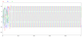
When the input voltage is 24v, 1.5A, and the output voltage is 9V and 1.5A, the motor is blocked. 

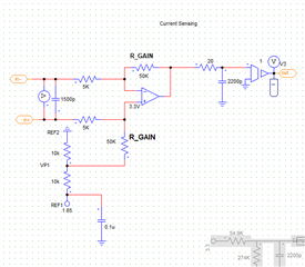
The customer believes that the main problem lies in the current sensing construction based on the circuit schematic simulation modeling of boostxl-3phganinv.

The internal circuit of INA240 is as follows:

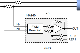
The customer cannot know the resistance value of each resistor in the above figure. Maybe the resistance value set in the simulation is wrong, which causes the output value of the current detection amplifier to exceed the range of 0-3.3v allowed by the ADC conversion.

Can you help determine if there is a problem with the hardware?

Best regards

  • Hi Green,

    The INA240A1 is a 20 V/V gain amplifier. Why are they wanting to break up it's parts and try to simulate it? 

    Best,

    Kevin

  • You might ask your customer refer to the example project below in motorControlSDK to use the boostxl-3phganinv for motor control. Please take a look at the user's guide about connecting the boostxl-3phganinv to a launchxl board though the guide is not for launchxl-f8069.

    C:\ti\c2000\C2000Ware_MotorControl_SDK_3_03_00_00\solutions\boostxl_3phganinv

  • Hi Kevin:

    I don’t think my client wants to break up INA240A1's parts.

    The customer built a circuit based on INA240A1 in the circuit simulation software according to the circuit diagram of boostxl-3phganinv. But this circuit based on INA240A1 will have a stall problem in actual operation. 

    The customer believes that this problem may be caused by his incorrect setting of the resistance value in the peripheral circuit of the INA240. So he wants us to check whether the schematic diagram of the peripheral circuit he built is correct?

    Or, what other problems can cause stalls?

    Best regards

  • Hi Yanming:

    Thank you for your advice.

    And since you are an expert in motor control, may you provide some other possibilities for motor stalls?

    Best regards

  • Which reference code are customer using? Or their own codes? Could you please provide more information about how to run the motor, and what appears during the motor is stall? Please post some testing waveform to show the questions if possible.

    If customer is using their own code, can the motor run well without load?

  • Hi Yanming:

    The customer’s simulation software uses PSIM, the speed simulation waveform is as follows, the given speed is 500r/min:

    The Lomberg positionless observer is used in the modeling process, and the back EMF obtained is as follows:

    The three-phase current waveform is as follows:

    The waveform has a great overshoot when the motor starts, and it cannot track the given speed quickly. When the generated code is downloaded to the circuit board, the motor is blocked and the current is large. The customer believes that there is no major problem with the simulation, and it is reasonable to say that the actual operation of the motor will not be a problem, but as soon as the code runs, the motor is blocked and there is a lot of noise.

    The attachment is the customer's code.

    DRV8305 PMSM InstaSPIN Lab11 (F28069) (C code).zip

    Best regards

  • On this forum we are able to support specific device and TI reference codes related questions. We are difficult to help to customer to evaluate the code they design, especially the code is automatic generated by the simulation tool.

    You might ask customer to run the example lab in motorWare since these labs have been validated.