This thread has been locked.

If you have a related question, please click the "Ask a related question" button in the top right corner. The newly created question will be automatically linked to this question.

TMS320F28377D: Block only one (A or B) ePWM channel with DCxEVT

Part Number: TMS320F28377D


Hi!
I ran into a problem when using DCAEVT1 and DCBEVT1 events.
I want to setup ePWM module to complementary operation mode with dead time.

Also l want to be able to block (set to HIZ state) either channel A switch or channel B switch by software independently.
According to the documentation, DCAEVT1 and DCBEVT1 events can be used for this purpose.

I set up ePWM module this way:
EPwm7Regs.TZCTL.bit.DCAEVT1 = 0;
EPwm7Regs.TZCTL.bit.DCBEVT1 = 0;


Switches blocking/deblocking is carried out this way:
EPwm7Regs.TZFRC.bit.DCAEVT1 = 1;
EPwm7Regs.TZCLR.bit.DCAEVT1 = 1;
EPwm7Regs.TZFRC.bit.DCBEVT1 = 1;
EPwm7Regs.TZCLR.bit.DCBEVT1 = 1;

Deadband module is set up this way:
EPwm7Regs.DBCTL.bit.IN_MODE = DBA_ALL; //0x0
EPwm7Regs.DBCTL.bit.POLSEL = DB_ACTV_HIC; //0x2
EPwm7Regs.DBCTL.bit.OUT_MODE = DB_FULL_ENABLE; //0x3


DCAEVT1 and DCBEVT1 flags in EPwm7Regs.TZFLG are set and cleared properly. But there is no reaction in ePWM outputs. Both A and B channels keep operating despite the flags. I could not find any other settings in the documentation that are necessary for these events to work. Can you help me with this problem?

  • Hello, 

    Due to the US Thanksgiving holiday, please expect a response by 11/30. 

    Thanks, 

    Anu

  • Hi Disona,

    Where in your program are you forcing the flag and clearing it? Note, that the action (high-z state) will only occur for the duration of the DCAEVT1/DCBEVT1 events.

    Best Regards,

    Marlyn

  • Thank you for the reply.

    The flags are forced and cleared in 1 millisecond ISR this way:
    - if debug variable is "0", the flag is cleared every 1 ms
    - else it is forced every 1 ms. debug1 and debug2 variables are changed manually.

    The flags are watched in debug3 variable.

    if (debug1) {
      EALLOW;
      EPwm7Regs.TZFRC.bit.DCAEVT1 = 1;
      EDIS:
    } else {
      EALLOW;
      EPwm7Regs.TZCLR.bit.DCAEVT1 = 1;
      EDIS;
    }

    if (debug2) {
      EALLOW;
      EPwm7Regs.TZFRC.bit.DCBEVT1 = 1;
      EDIS:
    } else {
      EALLOW;
      EPwm7Regs.TZCLR.bit.DCBEVT1 = 1;
      EDIS;
    }

    debug3 = EPwm7Regs.TZFLG.all;

    What do you mean "that the action (high-z state) will only occur for the duration of the DCAEVT1/DCBEVT1 events."?
    If I force the event by the software does it mean, that the PWM A or B output will be blocked only while this instruction is executed?

  • Hi Disona,

    I did this code and tested it. The EPWM outputs change to a high-z state whenever "applyForceCondition" is 1 else the condition will clear. Please compare this with what you have or test it on your setup to see if it works for you so we can narrow down the issue:

    //
    // Included Files
    //
    #include "F28x_Project.h"
    
    //
    // Globals
    //
    Uint32 applyForceCondition = 0;
    
    //
    // Function Prototypes
    //
    void InitEPwm1Example(void);
    void InitEPwmGpio_TZ(void);
    
    //
    // Main
    //
    void main(void)
    {
    //
    // Initialize System Control:
    // PLL, WatchDog, enable Peripheral Clocks
    // This example function is found in the F2837xD_SysCtrl.c file.
    //
        InitSysCtrl();
    
    //
    // Initialize GPIO:
    // For this case just init GPIO pins for ePWM1
    //
        InitEPwmGpio_TZ();
    
    //
    // enable PWM1
    //
        EALLOW;
        CpuSysRegs.PCLKCR2.bit.EPWM1=1;
        EDIS;
    
    //
    // Clear all interrupts and initialize PIE vector table:
    // Disable CPU interrupts
    //
        DINT;
    
    //
    // Initialize the PIE control registers to their default state.
    // The default state is all PIE interrupts disabled and flags
    // are cleared.
    // This function is found in the F2837xD_PieCtrl.c file.
    //
        InitPieCtrl();
    
    //
    // Disable CPU interrupts and clear all CPU interrupt flags:
    //
        IER = 0x0000;
        IFR = 0x0000;
    
    //
    // Initialize the PIE vector table with pointers to the shell Interrupt
    // Service Routines (ISR).
    // This will populate the entire table, even if the interrupt
    // is not used in this example.  This is useful for debug purposes.
    // The shell ISR routines are found in F2837xD_DefaultIsr.c.
    // This function is found in F2837xD_PieVect.c.
    //
        InitPieVectTable();
    
    //
    // Initialize the Device Peripherals:
    //
        EALLOW;
        CpuSysRegs.PCLKCR0.bit.TBCLKSYNC =0;
        EDIS;
    
        InitEPwm1Example();
    
        EALLOW;
        CpuSysRegs.PCLKCR0.bit.TBCLKSYNC =1;
        EDIS;
    
    //
    // User Code:
    //
        for(;;)
        {
            if (applyForceCondition == 1)
            {
                EALLOW;
                EPwm1Regs.TZFRC.bit.DCAEVT1 = 1;
                EPwm1Regs.TZFRC.bit.DCBEVT1 = 1;
                EDIS;
            }
            else
            {
                EALLOW;
                EPwm1Regs.TZCLR.bit.DCAEVT1 = 1;
                EPwm1Regs.TZCLR.bit.DCBEVT1 = 1;
                EDIS;
            }
        }
    }
    
    //
    // InitEPwm1Example - Initialize EPWM1 configuration
    //
    void InitEPwm1Example()
    {
        //
        // Enable TZ1 as one shot trip sources
        //
        EALLOW;
        EPwm7Regs.TZCTL.bit.DCAEVT1 = 0;  //High-Z
        EPwm7Regs.TZCTL.bit.DCBEVT1 = 0;  //High-Z
        EDIS;
    
        EPwm1Regs.TBPRD = 12000;                        // Set timer period
        EPwm1Regs.TBPHS.bit.TBPHS = 0x0000;             // Phase is 0
        EPwm1Regs.TBCTR = 0x0000;                       // Clear counter
    
        //
        // Setup TBCLK
        //
        EPwm1Regs.TBCTL.bit.CTRMODE = TB_COUNT_UPDOWN; // Count up
        EPwm1Regs.TBCTL.bit.PHSEN = TB_DISABLE;        // Disable phase loading
        EPwm1Regs.TBCTL.bit.HSPCLKDIV = TB_DIV4;       // Clock ratio to SYSCLKOUT
        EPwm1Regs.TBCTL.bit.CLKDIV = TB_DIV4;
    
        EPwm1Regs.CMPCTL.bit.SHDWAMODE = CC_SHADOW;    // Load registers every ZERO
        EPwm1Regs.CMPCTL.bit.LOADAMODE = CC_CTR_ZERO;
    
        //
        // Setup compare
        //
        EPwm1Regs.CMPA.bit.CMPA = 6000;
    
        //
        // Set actions
        //
        EPwm1Regs.AQCTLA.bit.CAU = AQ_SET;             // Set PWM1A on CAU
        EPwm1Regs.AQCTLA.bit.CAD = AQ_CLEAR;           // Clear PWM1A on CAD
    
        //
        // Setup the deadband
        //
        EPwm1Regs.DBCTL.bit.IN_MODE = DBA_ALL;         //0x0
        EPwm1Regs.DBCTL.bit.POLSEL = DB_ACTV_HIC;      //0x2
        EPwm1Regs.DBCTL.bit.OUT_MODE = DB_FULL_ENABLE; //0x3
    }
    
    //
    // InitEPwmGpio_TZ - Initialize EPWM1A/B GPIOs
    //
    void InitEPwmGpio_TZ(void)
    {
        EALLOW;
        GpioCtrlRegs.GPAPUD.bit.GPIO0 = 1;    // Disable pull-up on GPIO0 (EPWM1A)
        GpioCtrlRegs.GPAMUX1.bit.GPIO0 = 1;   // Configure GPIO0 as EPWM1A
        GpioCtrlRegs.GPAPUD.bit.GPIO1 = 1;    // Disable pull-up on GPIO1 (EPWM1B)
        GpioCtrlRegs.GPAMUX1.bit.GPIO1 = 1;   // Configure GPIO1 as EPWM1B
        EDIS;
    }
    
    //
    // End of file
    //

    What do you mean "that the action (high-z state) will only occur for the duration of the DCAEVT1/DCBEVT1 events."?
    If I force the event by the software does it mean, that the PWM A or B output will be blocked only while this instruction is executed?

    It means that the action you specify (in this case "high-z") will only be applied to the outputs while the DCAEVT1/DCBEVT1 flags are set. As soon as you clear the flags the output should go back to normal.

    Best Regards,

    Marlyn

  • Dear Marlyn, thank you for your assistance.


    As we understand, in your case you force the flag in the background task.
    Also you have no other tasks/ISRs in your code.
    As a result, "for(;;)" loop in your example is being executed without any pause.
    So in fact the DCAEVT/DCBEVT are forced every several CPU cycles.

    We tried to test your code on our setup.
    But we set or clear DCxEVT flags in 1 millisecond ISR instead of an endless loop.
    We found that the PWM outputs are blocked, but for a very short period of time.
    You can see in the figures that PWM outputs are blocked with 1 ms interval.
    Also you can see the enlarged waveform of the blocking moment.
    However, the DCAEVT1/DCBEVT1 flags remain set constantly when (applyForceCondition == 1).


    You can try to reproduce the problem and check PWM outputs blocking by modifying the user code in your example this way:

    //
    // User Code:
    //
        for(;;)
        {
            if (applyForceCondition == 1)
            {
                applyForceCondition = 0;
                EALLOW;
                EPwm1Regs.TZFRC.bit.DCAEVT1 = 1;
                EPwm1Regs.TZFRC.bit.DCBEVT1 = 1;
                EDIS;
            }
            else if (applyForceCondition == 2)
            {
                applyForceCondition = 0;
                EALLOW;
                EPwm1Regs.TZCLR.bit.DCAEVT1 = 1;
                EPwm1Regs.TZCLR.bit.DCBEVT1 = 1;
                EDIS;
            }
        }


    Here are some waveforms, that we got.

    1. Here we have our PWM output signals on A and B channels with ~250 Hz frequency.


    2. Now we try to force DCA event every 1 ms. Note that the time axis is 250 us/div, instead of 1 ms/div - we enlarged one PWM pulse to take a close look. We can see, that the yellow signal is blocked just for a moment (next to the first yellow cursor) and the it's unblocked again. And the same picture 1 ms after that (because we force the event every 1 ms).


    3. If we look even closer, we can see the duration of "blocked" signal - it's about 125 ns.
    The signal is falling slow, because we measure it not on the CPU output, but on the output of some pull-up/pull-down circuit on our control board:


    As we expect, the signal must remain blocked until we clear the event flag. But it doesn't work that way.

  • Hi Disona,

    Thank you for providing more information. What is your 1 millisecond ISR? Is it a timer ISR? If so, can I please see how that is being setup.

    Could you toggle some GPIOs at each case scenario (drive GPIO high when event is forced, drive GPIO low whenever event is cleared)? This is just for debug to ensure that the flags are being set for the desired duration.

    You also mentioned that "debug1 and debug2 variables are changed manually.". Is this through CCS expression window?

    Best Regards,

    Marlyn

  • Dear Marlyn, thank you for your attention to our problem.

    What is your 1 millisecond ISR? Is it a timer ISR? If so, can I please see how that is being setup.

    The 1ms ISR is generated by ePWM8. Here is the code:

     // 1 ms ISR
        EPwm8Regs.TBPRD = (((200000/2)/2)/4);
    
        EPwm8Regs.TBCTL.bit.CTRMODE = TB_COUNT_UPDOWN;
        EPwm8Regs.TBCTL.bit.HSPCLKDIV = TB_DIV1;
        EPwm8Regs.TBCTL.bit.CLKDIV = TB_DIV4;
    
        //Interrupt setup
        EPwm8Regs.ETSEL.bit.INTSEL = ET_CTR_ZERO;  // Select INT on Zero event
        EPwm8Regs.ETSEL.bit.INTEN = 1;    // Enable INT
        EPwm8Regs.ETPS.bit.INTPRD = ET_1ST;  // Generate INT on 1st event
    
        // Initializing interrupt
        EALLOW;
        PieVectTable.EPWM8_INT = (PINT)&msIsr;
        EDIS;
        PieCtrlRegs.PIEIER3.all |= M_INT8;  // ePWM8 - 1 kHz freq
        IER |= M_INT3;


    You also mentioned that "debug1 and debug2 variables are changed manually.". Is this through CCS expression window?

    No. We do not connect any JTAG-debuggers to the MCU during our tests.
    Instead we use CAN with CANopen protocol to communicate with the MCU.


    Could you toggle some GPIOs at each case scenario (drive GPIO high when event is forced, drive GPIO low whenever event is cleared)? This is just for debug to ensure that the flags are being set for the desired duration.

    Sure.

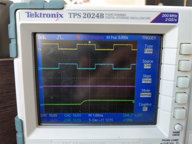
    On the waveforms below we show folowwing signals:

    • Channel 1 (yellow) is PWM A output
    • Channel 2 (blue) is PWM B output
    • Channel 3 (magenta) is GPIO (GPIO41) that is set when DCAEVT1 is forced
    • Channel 4 (green) is GPIO (GPIO40) that is set when DCBEVT1 is forced

    Here is our code to toggle gpio:

    if (cpu01.debug.debugI1 == 1)
        {
            EALLOW;
            EPwm7Regs.TZFRC.bit.DCAEVT1 = 1;
            EDIS;
            GpioDataRegs.GPBCLEAR.bit.GPIO41 = 1;
        }
        else
        {
            EALLOW;
            EPwm7Regs.TZCLR.bit.DCAEVT1 = 1;
            EDIS;
            GpioDataRegs.GPBSET.bit.GPIO41 = 1;
        }
    
    if (cpu01.debug.debugI2 == 1)
        {
            EALLOW;
            EPwm7Regs.TZFRC.bit.DCBEVT1 = 1;
            EDIS;
            GpioDataRegs.GPBCLEAR.bit.GPIO40 = 1;
        }
        else
        {
            EALLOW;
            EPwm7Regs.TZCLR.bit.DCBEVT1 = 1;
            EDIS;
            GpioDataRegs.GPBSET.bit.GPIO40 = 1;
        }

    IMPORTANT NOTE 1: on our control board GPIO40 and GPIO41 go to inverters, so we use "GPIOCLEAR" to generate HIGH signal on the waveforms, and "GPIOSET" to generate LOW signal.
    IMPORTANT NOTE 2: the mentioned inverters are open-drain schemes, so the rising fronts of the 3 and 4 channels on the waveforms are sloped.

    Here are the waveforms:

    1. Here we have PWM outputs A (yellow) and B (blue) switching with ~250 Hz frequency. Then we set "debug1 = 1" to generate "DCAEVT1". You can see that GPIO41 (magenta) goes high at these moment and stays like that. But PWM channel A (yellow) continues switching:

    2. Then we set "debug1 = 0" to clear "DCAEVT1" event. GPIO41 (magenta) goes low as expected. PWMA (yellow) keeps switching.

    3. Now we set "debug2 = 1" to generate "DCBEVT1". You can see that GPIO40 (green) goes high at these moment and stays like that. But PWM channel B (blue) continues switching:

    4. Finally, we set "debug2 = 0" to clear "DCBEVT1" event. GPIO40 (green) goes low as expected. PWMB (blue) keeps switching.

    As you can see in the code, when GPIO40 and GPIO41 are high on the waveforms, DCA and DCB events are forced every 1 ms and never cleared.
    But on the waveforms we still see them switching.


    If you wish, you can reproduce the problem even in the infinite while(1)/for(;;) loop using the code from my previous message.
    The idea is not to force DAC/DCB events every few CPU cycles (which are 200 MHz freq), but only once, when a variable is changed.

        for(;;)
        {
            if (applyForceCondition == 1)
            {
                applyForceCondition = 0;
                EALLOW;
                EPwm1Regs.TZFRC.bit.DCAEVT1 = 1;
                EPwm1Regs.TZFRC.bit.DCBEVT1 = 1;
                EDIS;
            }
            else if (applyForceCondition == 2)
            {
                applyForceCondition = 0;
                EALLOW;
                EPwm1Regs.TZCLR.bit.DCAEVT1 = 1;
                EPwm1Regs.TZCLR.bit.DCBEVT1 = 1;
                EDIS;
            }
        }

  • Hi Disona,

    Thank you for detailed debug. I will have access to hardware tomorrow and will provide an update then once I duplicate the issue you are seeing.

    Best Regards,

    Marlyn

  • Hi Disona,

    I was able to duplicate what you are seeing. I'll work on finding a route cause now that I can duplicate the issue.

    I will provide another update for you on Monday.

    Best Regards,

    Marlyn

  • Hi Marlyn

    That's great! We will wait for the results.

  • Hi Disona,

    Thank you for your patience. Today I altered my code to operate in a similar fashion as yours. 

    EPWM1 (Channel 1) is ~250Hz and EPWM2 (Channel 2) is ~1000Hz. 

    The Interrupt for EPWM2 is generating the force and clear trip zone flags for EPWM1

    Even when 'debug1' is set as one and the DCAEVT1 flag is set, the output remains as in the screenshot above (duplicating the results you see).

    After looking at various options for why this is happening I believe I need to loop in our design team. I will provide an update by Wednesday with their response. I just wanted to touch bases with you and let you know this is something I am working on. 

    Best Regards,

    Marlyn

  • Hi Marlyn

    Thank you for keeping us up to date!

  • Hi Disona,

    I don't have an update yet but will let you know as soon as I hear back from our design team.

    Bet Regards,

    Marlyn

  • Hi Disona

    I wanted to provide you with a possible work-around while we wait for the response from the design team. Please take a look at the code below, specifically the msISR() which is the ISR that is forcing/clearing the trip zone event. I force a one-shot event and clear it but change the TZA/TZB actions according to "debug1" and "debug2" to control the state of ePWM1A and ePWM1B independently.

    I will be out next week for the holidays but have asked a team member to monitor this thread in case you have questions or we hear back from design.

    //
    // Included Files
    //
    #include "F28x_Project.h"
    
    //
    // Globals
    //
    Uint32 debug1=0;
    Uint32 debug2=0;
    Uint32 debug3=0;
    Uint32 EPwm2TimerIntCount;
    
    
    //
    // Function Prototypes
    //
    void InitEPwm1Example(void);
    void InitEPwm2Example(void);
    void InitEPwmGpio_TZ(void);
    
    __interrupt void msISR(void);
    
    //
    // Main
    //
    void main(void)
    {
        //
        // Step 1. Initialize System Control:
        // PLL, WatchDog, enable Peripheral Clocks
        // This example function is found in the F2837xD_SysCtrl.c file.
        //
            InitSysCtrl();
    
        //
        // Step 2. Initialize GPIO:
        // This example function is found in the F2837xD_Gpio.c file and
        // illustrates how to set the GPIO to its default state.
        //
        //    InitGpio();
    
        //
        // enable PWM1, PWM2
        //
            CpuSysRegs.PCLKCR2.bit.EPWM1=1;
            CpuSysRegs.PCLKCR2.bit.EPWM2=1;
    
        //
        // For this case just init GPIO pins for ePWM1, ePWM2
        // These functions are in the F2837xD_EPwm.c file
        //
            InitEPwmGpio_TZ();
    
        //
        // Step 3. Clear all interrupts and initialize PIE vector table:
        // Disable CPU interrupts
        //
            DINT;
    
        //
        // Initialize the PIE control registers to their default state.
        // The default state is all PIE interrupts disabled and flags
        // are cleared.
        // This function is found in the F2837xD_PieCtrl.c file.
        //
            InitPieCtrl();
    
        //
        // Disable CPU interrupts and clear all CPU interrupt flags:
        //
            IER = 0x0000;
            IFR = 0x0000;
    
        //
        // Initialize the PIE vector table with pointers to the shell Interrupt
        // Service Routines (ISR).
        // This will populate the entire table, even if the interrupt
        // is not used in this example.  This is useful for debug purposes.
        // The shell ISR routines are found in F2837xD_DefaultIsr.c.
        // This function is found in F2837xD_PieVect.c.
        //
            InitPieVectTable();
    
        //
        // Interrupts that are used in this example are re-mapped to
        // ISR functions found within this file.
        //
            EALLOW; // This is needed to write to EALLOW protected registers
            PieVectTable.EPWM2_INT = &msISR;
            EDIS;   // This is needed to disable write to EALLOW protected registers
    
        //
        // Step 4. Initialize the Device Peripherals:
        //
            EALLOW;
            CpuSysRegs.PCLKCR0.bit.TBCLKSYNC =0;
            EDIS;
    
            InitEPwm1Example();
            InitEPwm2Example();
    
            EALLOW;
            CpuSysRegs.PCLKCR0.bit.TBCLKSYNC =1;
            EDIS;
    
        //
        // Step 5. User specific code, enable interrupts:
        // Initialize counters:
        //
            EPwm2TimerIntCount = 0;
    
        //
        // Enable CPU INT3 which is connected to EPWM1-3 INT:
        //
            IER |= M_INT3;
    
        //
        // Enable EPWM INTn in the PIE: Group 3 interrupt 1-3
        //
            PieCtrlRegs.PIEIER3.bit.INTx2 = 1;
    
        //
        // Enable global Interrupts and higher priority real-time debug events:
        //
            EINT;  // Enable Global interrupt INTM
            ERTM;  // Enable Global realtime interrupt DBGM
    
        //
        // Step 6. IDLE loop. Just sit and loop forever (optional):
        //
            for(;;)
            {
    
            }
    }
    
    
    //
    // Interrupt for EPWM2
    //
    __interrupt void msISR(void)
    {
        EPwm2TimerIntCount++;
        
        // Debug 1 -> Controls ePWMA
        // Debug 2 -> Controls ePWMB
    
        EALLOW;
        if (debug1 == 1 || debug2 == 1)
        {
          // Setup correct actions
          if (debug1 == 1 & debug2 != 1)
          {
              EPwm1Regs.TZCTL.bit.TZA = 0;  // High-Z
              EPwm1Regs.TZCTL.bit.TZB = 3;  // Do Nothing
          }
          else if (debug2 == 1 && debug1 !=1)
          {
              EPwm1Regs.TZCTL.bit.TZA = 3;  // Do nothing
              EPwm1Regs.TZCTL.bit.TZB = 0;  // High-Z
          }
          else if (debug1==1 && debug2==1)
          {
              EPwm1Regs.TZCTL.bit.TZA = 0;  // High-Z
              EPwm1Regs.TZCTL.bit.TZB = 0;  // High-Z
          }
          // Force one-shot event
          EPwm1Regs.TZFRC.bit.OST = 1;
        }
        else
        {
          // Clear one-shot event
          EPwm1Regs.TZCLR.bit.OST = 1;
          EPwm1Regs.TZCTL.bit.TZA = 0;  // High-Z
          EPwm1Regs.TZCTL.bit.TZB = 0;  // High-Z
        }
    
        EDIS;
    
        debug3 = EPwm1Regs.TZFLG.all;
    
        //
        // Clear INT flag for this timer
        //
        EPwm2Regs.ETCLR.bit.INT = 1;
    
        //
        // Acknowledge this interrupt to receive more interrupts from group 3
        //
        PieCtrlRegs.PIEACK.all = PIEACK_GROUP3;
    }
    
    //
    // InitEPwm1Example - Initialize EPWM1 configuration
    //
    void InitEPwm1Example()
    {
        EPwm1Regs.TBPRD = 12500;                        // Set timer period 12000
        EPwm1Regs.TBPHS.bit.TBPHS = 0x0000;             // Phase is 0
        EPwm1Regs.TBCTR = 0x0000;                       // Clear counter
    
        //
        // Setup TBCLK
        //
        EPwm1Regs.TBCTL.bit.CTRMODE = TB_COUNT_UPDOWN; // Count up
        EPwm1Regs.TBCTL.bit.PHSEN = TB_DISABLE;        // Disable phase loading
        EPwm1Regs.TBCTL.bit.HSPCLKDIV = TB_DIV4;       // Clock ratio to SYSCLKOUT
        EPwm1Regs.TBCTL.bit.CLKDIV = TB_DIV4;
    
        EPwm1Regs.CMPCTL.bit.SHDWAMODE = CC_SHADOW;    // Load registers every ZERO
        EPwm1Regs.CMPCTL.bit.LOADAMODE = CC_CTR_ZERO;
    
        //
        // Setup compare
        //
        EPwm1Regs.CMPA.bit.CMPA = 6250;
    
        //
        // Set actions
        //
        EPwm1Regs.AQCTLA.bit.CAU = AQ_SET;             // Set PWM1A on CAU
        EPwm1Regs.AQCTLA.bit.CAD = AQ_CLEAR;           // Clear PWM1A on CAD
    
        //
        // Setup the deadband
        //
        EPwm1Regs.DBCTL.bit.IN_MODE = DBA_ALL;         //0x0
        EPwm1Regs.DBCTL.bit.POLSEL = DB_ACTV_HIC;      //0x2
        EPwm1Regs.DBCTL.bit.OUT_MODE = DB_FULL_ENABLE; //0x3
    
        //
        // Setup Trip Zone
        //
        //
        // Enable TZ1 as one shot trip sources
        //
        EALLOW;
        EPwm1Regs.TZCTL.bit.TZA = 0;  //High-Z
        EPwm1Regs.TZCTL.bit.TZB = 0;  //High-Z
        EDIS;
    }
    
    
    //
    // InitEPwm2Example - Initialize EPWM2 configuration
    //
    void InitEPwm2Example()
    {
        // 1 ms ISR
        EPwm2Regs.TBPRD = (((200000/2)/2)/4);
    
        EPwm2Regs.TBCTL.bit.CTRMODE = TB_COUNT_UPDOWN;
        EPwm2Regs.TBCTL.bit.HSPCLKDIV = TB_DIV1;
        EPwm2Regs.TBCTL.bit.CLKDIV = TB_DIV4;
    
        //
        // Setup compare
        //
        EPwm2Regs.CMPA.bit.CMPA = 6250;
    
        //
        // Set actions
        //
        EPwm2Regs.AQCTLA.bit.CAU = AQ_SET;             // Set PWM1A on CAU
        EPwm2Regs.AQCTLA.bit.CAD = AQ_CLEAR;           // Clear PWM1A on CAD
    
        //Interrupt setup
        EPwm2Regs.ETSEL.bit.INTSEL = ET_CTR_ZERO;  // Select INT on Zero event
        EPwm2Regs.ETSEL.bit.INTEN = 1;    // Enable INT
        EPwm2Regs.ETPS.bit.INTPRD = ET_1ST;  // Generate INT on 1st event
    }
    //
    // InitEPwmGpio_TZ - Initialize EPWM1A/B GPIOs
    //
    void InitEPwmGpio_TZ(void)
    {
        EALLOW;
        GpioCtrlRegs.GPAPUD.bit.GPIO0 = 1;    // Disable pull-up on GPIO0 (EPWM1A)
        GpioCtrlRegs.GPAMUX1.bit.GPIO0 = 1;   // Configure GPIO0 as EPWM1A
        GpioCtrlRegs.GPAPUD.bit.GPIO1 = 1;    // Disable pull-up on GPIO1 (EPWM1B)
        GpioCtrlRegs.GPAMUX1.bit.GPIO1 = 1;   // Configure GPIO1 as EPWM1B
    
        GpioCtrlRegs.GPAPUD.bit.GPIO2 = 1;    // Disable pull-up on GPIO2 (EPWM2A)
        GpioCtrlRegs.GPAMUX1.bit.GPIO2 = 1;   // Configure GPIO2 as EPWM2A
        GpioCtrlRegs.GPAPUD.bit.GPIO3 = 1;    // Disable pull-up on GPIO3 (EPWM2B)
        GpioCtrlRegs.GPAMUX1.bit.GPIO3 = 1;   // Configure GPIO3 as EPWM2B
        EDIS;
    }
    
    //
    // End of file
    //
    

    Best Regards,

    Marlyn

  • Hi Marlyn

    Thank you for this work-around.

    For now we just de-mux PWM GPIOs into "Input" mode, when we want to turn off PWM.

    This works ok, but we still would like to get the answer for our DCA/DCB question.

  • DCA/BEVT force will only be a short pulse when using SW FRC. Then the DCxEVT condition will no longer be on. Therefor the ePWM will resume. If using the RAW DCxEVT action, you will only see your ePWM disable for the short amount of time that the SW FRC pulse is propagating through. There is no continuous SW FRC for DCxEVT. What you are seeing is expected. You would have to use the OST latch to keep the SW FRC active.

    Nima

  • Thank you for the answer.

    Ok then, if this works as intended, we have no other option than to de-mux GPIO.
    Re-initing TZA/TZB is not our case, because we need to have ability to turn off the switches when want AND block them in HW when fault signals comes from the switch.
    Therefore we cannot use the method, that Marlyn had suggested.

    But we are puzzled with such behaviour.
    Could you please provide any usecase where one can need such a short blocking pulse?

    Because we expected, that the TZ condition will stay as long, as FLG remains set.
    And the documentation on this subject is not clear, as we think.

  • The FRC for DCxEVT is meant to be used along with CBC anc OST and not the RAW DCxEVT. That is why there arent any useful cases, other than introducing some GLITCHES and making sure that the DCFILT signal can filter them out.

    Nima

  • Ah, ok!
    Thank you!