This thread has been locked.

If you have a related question, please click the "Ask a related question" button in the top right corner. The newly created question will be automatically linked to this question.

TMS320F28069M: Own made can_flash_programmer gives unwanted result

Part Number: TMS320F28069M
Other Parts Discussed in Thread: TMS320F28335, C2000WARE

Dear sir of madam,

I have tried to make a custom adaptation to the serial_flash_programmer example of TI. This customization was transforming it into a flashprogrammer that works within our system by transmitting CAN messages in a special format that exists in our system. The result we are trying to achieve is making our driveline firmware remote updatable. Our driveline firmware runs on 2 TMS320F28069M processors on a custom board both connected to a single CAN connector for communication.

To give a better explanation of the system:
Our main motherboard is using a Intel atom processor. This motherboard is responsible for all the tasks in our robots. Between our motherboard and driveline PCB stands a STM controller which transforms the UART messages send by the Intel motherboard to a CAN message that can be used by our TMS320f28069M controllers on the driveline. 

So for starting this project I have done some research and decided to make an adaptation of the serial_flash_programmer by making it into a can_flash_programmer. The goal is to make this software run on the Intel motherboard so that it can download the new firmware onto the driveline by sending the correct messages to our STM controller, which will then send it to our driveline. For this flash_programmer I have removed the first step in which the programmer downloads the flash kernel to the board. We have done this because we want the flash kernel to exist in our driveline firmware so that we dont have to put the board in CAN Boot Mode. 

I have tested this concept by downloading the SCI flash kernel to the board using the debug probe. And after that running the serial_flash programmer from my laptop with a USB to UART bridge. This serial_flash_programmer was without the step that downloads the sci_flash_kernel and I have confirmed this works, on both our own PCB and the TMSDOCK28069 Dev Board.

After that I started changing the serial_flash_programmer to a can_flash_programmer. I did this by constructing a UART message in the way our STM controller understands that it is a CAN message which needs to be sent to the driveline board. Our message consists of a 4 byte header a 2 byte ID followed by 8 bytes of data finished with a checksum. The header and ID are constant variables and the checksum is calculated in the code itself. Since the CAN module on the F28069M reads 2 bytes at a time I have changed it as followed:|

TI's example serial_flash_programmer:
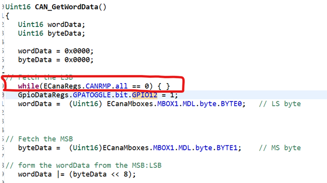
my own can_flash_programmer:

This makes it read 2 bytes each time that will be used to construct the message by doing the following:

This refers to the following function that constructs our message:

Then we want to write the message to the STM controller I do this by first constructing a bytearray in the following way:


And after that I run this writeFIle command:


since CAN does not use a checksum and reads 2 bytes at a time instead of 1 I have also changed the rest of the flash_programmer to the following, the code shown is the code starting form calling the writeFile from above:

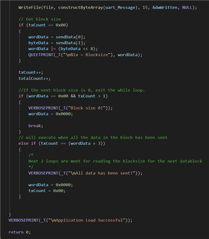
I have also checked with realterm and cmd that everything constructs and sends like I expected it to be and using a PCAN viewer connected to my STM controller I can confirm it indeed sends the CAN messages.
This is an example of what I get:

CMD:
  
Note that the fd at the end here is the overflow which will never be sent to the STM controller


Realterm

PCAN Viewer:

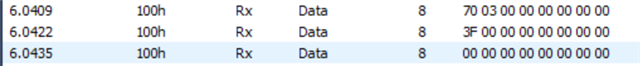
This resembles the output of the STM controller, so this is the input from the TMS controller through the CAN connection.

But when I try to do this on de Dev Board or our own board (with the can_flash_kernel downloaded to it) it does not seem to work and I get no output. (I am simply trying to flash the Example_f2806xLEDBlink).

I hope I have provided you with enough information and hope you can help me with this, If anything is unclear please ask and I will provide the missing information. 

Kind regards,
Guilliam

  • Hi Guilliam, 

    Have you tried reading the RX pin configured on the F2806x device to see what is happening? The data is being transmitted but not received correct? It would be good to see what is happening on the RX pin via oscilloscope. 

    In addition, are the correct GPIO pins configured on F2806x for CAN?

    Thanks, 

    Anu

  • Hi Anu,

    Thanks for the suggestion I will check the RX with an oscilloscope, I will sent my results from this. I am shure the problem is not in the GPIO pins. This is because I programm the can_flash_kernel onto the board with the debug probe. After that I sent the data via the flash programmer. This worked perfectly with SCI but with the CAN it doesn't. So like I said I will check the RX and send you my results.

    Kind regards,
    Guilliam

  • Guilliam, 

    Sure that sounds good. 

    Anu

  • Hi Anu, this is the result I get from the oscilloscope:


    The weird thing is that the 2 first signals are digital but the other signals is more in a sinus wave which isn't correct if im right. So I was wondering what could be the problem?

    Thanks,
    Guilliam

  • Guilliam,

                    I think communication between the STM board and the Driveline board (which contains two 28069 devices) is done through CAN. i.e. there are at least 3 nodes on the CAN bus (two 28069 and one STM controller). Is my understanding correct?

    I presume the waveform you attached was measured at the CANRX pin of (one of the) 28069 device. Forget CAN,  this doesn't even look like a digital signal. Would you be able to provide the circuit for the CAN connection between the STM controller and Driveline board? You could share it privately with me by initiating a friendship request.

    Have you looked at the debug tips in www.ti.com/lit/spra876?

  • Hi Hareesh,


    To answer the first question about the nodes you are correct. In the real situation we have a STM controller that sends the CAN messages to the driveline board. This STM controller and board are connected with a CANbus indeed.


    The waveform I attached is the signal sent to the Dev board. I connected the scope to the jumper cable that connects the MCP2551 to GPIO30(CANRX) of the devboard. Today though we found out there was a problem in the connection between the parts. We fixed this and got a much more approachable output:
     This is the signal we get on the Dev board.

    We also read the RX on our driveline board. This gave the following output:
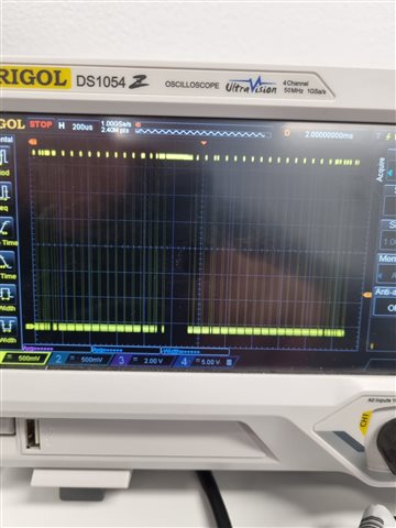
     This is the signal we get on the driveline board.

    As you see it is quite the same but not exactly. So I am wondering what could cause this. I am now trying to get my hands on an oscilloscope with a CAN trigger/decoder for better understanding but cannot guarantee being able to get one. 
    I will send you our circuit in private.

    Update:

    I also just found out something I did not expect. I tried to read the TX pin on the driveline board just to verify that nothing is being transmitted. I expect nothing to be transmitted since this is not in the flash kernel so I should not receive anything on the TX I thought. Could you please give some explanation for this behavior. This is what I got as output while reading the TX:
      

    Thanks,
    Guilliam

  • I went further with some debugging after finding out about the TX pin. I did this by checken where in the can flash kernel the program gets stuck by toggling one of the leds on the board. And I found out it got stuck in the getworddata at the loop where it checks the RMP:


    At line 300 I toggle the bit. When I put this line before the while loop at line 299 the led goes on. When I place the line in the brackets at the while loop the led goes on. But when it is placed after the while loop the led never goes on. Therefore I assume that there are no incoming messages. 

  • Guilliam,

                    The waveform looks more like CAN now. I agree that you would benefit from a scope that can natively decode CAN waveforms. The waveform on the TX pin and the RX pin will seldom be exactly identical. (1) This is because of the ACK bit which is driven dominant by any receiver. Refer to Figure 2-6. Waveform at the CANRXA Pin in www.ti.com/lit/sprace5. (2) The difference in waveforms can also be observed during the arbitration phase, if there is more than one node competing for the bus. Note that any/every node on the bus will acknowledge a frame. I have explained this clearly in my Application reports. A good reference for waveforms is www.ti.com/lit/spracq3

    On a different note, I am bit lost as to exactly what help you need from me. I am happy to help you with any CAN hardware related query, but may not be able to help with issue related to your custom bootloader.

  • Understand C3 and C6 are capacitors. My question was why are they needed on the CANRX pin. The capacitors have the effect of increasing the rise/fall time of the CAN signal at the CANRX pin. May not be the reason for the issues you are facing, but wanted to bring it to your attention anyway. 

    Here is my suggestion to you for debugging this issue:

    First, check if the two 28069 MCUs are able to communicate to each other. i.e. don’t even connect the STM MCU. My App. Report www.ti.com/lit/spra876 has tested examples for both Transmit and Receive. Note that the examples were written for the TMS320F28335 device. However, they can be easily adopted for any 28x device with eCAN, provided you take care of the change in SYSCLKOUT speed and the resultant changes warranted for the CANBTC register. 

    Once you have confirmed communication between the two 28069 devices, try communicating between one 28069 and the STM MCU. It does not matter who is transmitting and who is receiving. Transmit something simple. Do not try your bootloader. Look through the debug tips in SPRA876 carefully for suggestions. All the best.

  • Hi Hareesh,

    We already checked if our MCU's on the board are able to communicate with the STM MCU. We verified this by connecting the STM to the board with the current firmware installed and we got incoming messages which we verified with Realterm. So this should not be the problem. The problem really lays in the receiving end of the board but also the Dev board. So the question is probably in the software I think? Do you agree with me or not, zo yes where do you think it could be?

    Besides this I have tried getting the example CAN_RXLOOP to work but can't seem to get it working. I am not quite shure what needs to be changed in the SYSCLKOUT and CANBTC or other parts of the program to make it work on my TMS320F28069M board. I might look over things that I shouldn't so I hope you could help me on the way a little. Sorry for the many questions just a Intern/student curious to learn Grin.

    Thanks,
    Guilliam

  • If you have already verified CAN communication between the 28069 MCU(s) and the STM MCU, the problem is indeed in software, where I am afraid I won’t be of much help.

  • Hi Anu,

    Could you maybe support me since this is probably a software related issue? And since you were the first to reply on this question? Because I cannot get my head around what might be the problem an neither does my supervisor.

    I have also tried to debug where the program gets stuck on the developmentboard by doing the same LED indication I tried on our own board, as stated in my question from 7 days ago. I changed the GPIO to 34 because that is the correct one for the devBoard but strangely enough this doesnt work then. I don't know why but even if I toggle the led before the loop it doesnt turn on. Do you maybe know what is the diffrence in this might be? The only diffrence I can find between our own board and the devBoard is that the devBoard has a tms320f28069MPZT and the devBoard a tms320f28069UPZT. I tried to find the diffrence between these but I couldn't find anything that might cause this problem. I might be wrong but would be more than happy to hear this from you.

    Thanks,
    Guilliam

  • Guilliam, 

    Is it possible to load the CAN kernel via JTAG in CCS and pause execution once the transmit has occurred? If the kernel is not receiving anything we need to first find out where the program is stuck. 

    Thanks

    Anu

  • Hi Anu,

    The kernel is sadly enough not receiving anything. I have already loaded the kernel on both boards using the JTAG debug probe. To see where the programm gets stuck I coded a line to turn on the led once it receives anything but that does not work. It stops at this while loop in the GetWordData in the CAN_Boot from the can_flash_kernel.


    When I put the line that comes after that (the line that turns on the led) in front of the loop the led goes on. But when I put it after the led and I send a CAN message nothing happens. And I have verified with the oscilloscope that the RX pin receives a signal. So what I might think is something goes wrong in the pheriperal settings for the eCAN module but I don't see anything strange in there. What do you think might be the problem?

    Thanks,
    Guilliam

  • Guilliam, 

    Can you compare the peripheral initialization for the CAN module in the CAN_Boot.c file located at C2000Ware_xx\libraries\boot_rom\f2806x\v1_1\rom_sources\source with the initialization in the flash kernel and see if there are any differences? If the RX pin is receiving a signal but the CAN module is not receiving anything the only place I can think that something is off is the initialization. The other possibility is that the GPIO pins are not getting correctly linked to the CAN module. The CAN_Boot file mentioned above should have reference code for CAN initialization and setting GPIO pins, can you take a look?

    Thanks

    Anu

  • Anu,

    I have compared the initialization of the flash kernel with the CAN_Boot.c in the boot_ROM folder. And it is identical. The only difference is the bittiming. 


    White is the can_flash_kernel CAN_Boot.c    Black is the rom_source CAN_Boot.c|

    I have also tried to put the timings from the rom_source in there but this doesnt make a difference. And we have verified that the timings are correct for our board. I have verified this by implementing one simple CAN message that will be sent after the CAN_Init function is done. I have verified the board sends the correct message with a PCAN Viewer. After this I have placed the message in the CAN_GetWordData funtion before the  while(ECanaRegs.CANRMP.all == 0) loop. This works fine and the board sends us the correct message. The problem really lays in the receiving end because it never gets out of the  while(ECanaRegs.CANRMP.all == 0) loop. I verified this just like toggling the led by sending the message after the lop.

    Besides that I dont think the GPIO pins are the problem as well. The can_flash_kernel links the GPIO pins 30 to RX and 31 to TX in the same way the rom_source does. And transmitting works fine as said above. 

    So I am really clueless to what it might be. Do you know what could be the problem?

    Thanks,
    Guilliam

  • Guilliam, 

    Thanks for the details. I will check with the Boot ROM expert for the CAN bootloader and see if there is anything specific that needs to be done to be able to get past that line, since the CAN Bootloader uses the same GetWordData function and let you know what I find out. 

    Thanks

    Anu

  • Hi Anu,

    First of all hope you have had a wonderfull christmas time. I found out what the problem was and the flash kernel is now receiving messages as it should. The problem was that in the FLASH2806x_API_Config.h the clockrate was not correct. I cannot believe how I have looked over this since it was such an obvious cause of the problem. But I found it out while reading this report: https://dev.ti.com/tirex/explore/node?node=ALsdJksktMrgurCkszgwqw__gYkahfz__LATEST. Luckily it now works. Thank you for all the support and advise. And I will now see this thread as resolved.

    Thanks,
    Guilliam