This thread has been locked.

If you have a related question, please click the "Ask a related question" button in the top right corner. The newly created question will be automatically linked to this question.

TMS320F28335: ADC issues

Part Number: TMS320F28335
Other Parts Discussed in Thread: TMS320F28334

Hi,

we've been working perfectly using TMS320F28335 into our advanced stepper driver during several years.

Now, with the problems on the supply chain I'm trying to use TMS320F28334  with the same package.

But I've found that ADC is not working properly. In our application, conversion is synchronized with PWM.

I've adapted the project to use this new model changing only gel and linker files. The working code is exactly the same.

What I should change to use this DSP? In theory only change the memory size!

Regards.

  • What I should change to use this DSP? In theory only change the memory size!

    Does your application use eCAP5 or eCAP6 (either the 32-bit capture inputs or auxiliary PWM outputs)?

    The datasheet shows the TMS320F28335 has eCAP1/2/3/4/5/6, but the TMS320F28334 only has eCAP1/2/3/4:

  • Hi, Chester,

    my application uses EPWM1A, EPWM2A, EPWM3A, EPWM4A and the current measurement voltage arrive to ADCINA2 and ADCINA3

    Thanks

  • Fermin,

    Can you describe what is happening on the F28334 that is causing issues with the ADC?  From your post, it sounds like the timing of the results is not consistent between the F28335 vs the F28334?  It will help to have this clarity.  There is no difference in the ADC or PWM between these 2 devices.

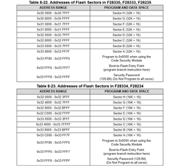
    While there is physically 1/2 the flash on the F28334 vs the F28335 the sector sizes are also 1/2 such that there are still 8 sectors for better erase flexibility.  Other than the eCAP mentioned previously this is the only other difference between the 2 devices.

    Just giving ideas at this point, but is there some embedded erase in your code that may not have taken this into account when porting?

    Best,

    Matthew

  • Hi,

    I'm generating 2 PWM signals to control the current in two coils.

    Synchronized with these PWMs I measure two voltages corresponding to the generated currents and extract the conversion value in the ISR as follows:

    interrupt void ADC_ISR(void)
    {

       Adc1Res = AdcRegs.ADCRESULT1 >> 4; // store results global
       Adc2Res = AdcRegs.ADCRESULT0 >> 4;

    // Reinitialize for next ADC sequence
        AdcRegs.ADCTRL2.bit.RST_SEQ1 = 1;       // Reset SEQ1
        AdcRegs.ADCST.bit.INT_SEQ1_CLR = 1;         // Clear INT SEQ1 bit
        PieCtrlRegs.PIEACK.all = PIEACK_GROUP1; // Acknowledge interrupt to PIE

    }

    And now, when I take this  Adc1Res or Adc2Res the value don't change, always = 2339

    Revising my adapted 28334_RAM_lnk.cmd the change is:

    //ORIGINAL

       //RAML1      : origin = 0x009000, length = 0x001000
       //RAML2      : origin = 0x00A000, length = 0x001000
       //RAML3      : origin = 0x00B000, length = 0x001000

    //ADAPTED
       RAML1      : origin = 0x009000, length = 0x003000    //added space for variables stored on .text space
       RAML2      : origin = 0x00C000, length = 0x001000    //to permit compilation
       RAML3      : origin = 0x00D000, length = 0x001000

    I may have made a mistake with the size assignment for each zone. But, I've tried also with original F28334.cmd and also doesn't work either.

    And responding to your last question, I've only change the linker files because I finished this development few years ago and I'm not able to change nothing more now.

    Thanks.

  • RAML2 and RAML3 are also accessible by the DMA, is there a possibility in the earlier code on the F28335 that these were allocated for some DMA use and that is over-writing the data?

    When you see 2339 is it from the Adc1Res variable for from the ADCRESULT directly?  Would you be able to set a breakpoint in the code at this section in the ADC_ISR to confirm if the ADCRESULT is also stuck?

    If you can also check the ADCINREFP/REFM pins and note the voltage we can make sure the ADC is powered up correctly.

    Best,

    Matthew

  • Hi,

    I've ensured all the possible hardware issues before including voltages on ADCINREFP/REFM... I've made this mistake several times before!! ;-)

    I can stop using breakpoint and from this stop I see the value of 2339 but I'll repeat the test to respond your question in a sure way about ADCRESULT.

    I use DMA for SPI communications but at the moment of test the secondary microcontroller where not sending or receiving data.

    Thanks.

  • Hi,

    now it's time to put on the worm suit!!!

    The voltage on ADCRFM were not correct because there was a very small crossover between the ADCREXT input resistor and the ADCREFP filter capacitor.

    Now the 28334 measures perfect as the 28335!

    By the way, what would be a good memory allocation to work from RAM during tests?

    Instead this:

    RAML1 : origin = 0x009000, length = 0x003000 //added space for variables stored on .text space
    RAML2 : origin = 0x00C000, length = 0x001000 //to permit compilation
    RAML3 : origin = 0x00D000, length = 0x001000

    Thanks.

    Fermin

  • Fermin,

    The RAM allocation is fine, all RAM on this device is 0 WaitState, so there's no concern there.  L4 - L7 are accessible by the DMA, so if you wanted to read the ADC results with the DMA you could allocate some buffer space there so the DMA can write them for the CPU to read when it needs to.

    Best,

    Matthew

  • Thanks you so much.