This thread has been locked.

If you have a related question, please click the "Ask a related question" button in the top right corner. The newly created question will be automatically linked to this question.

INSTASPINUNIVERSALGUI: Problems with parameters identified in the GUI

Part Number: INSTASPINUNIVERSALGUI
Other Parts Discussed in Thread: MOTORWARE, TMDSHVMTRINSPIN

Dear team:

My customer has the following problems with some parameters identified by the GUI:

1, Can the moment of inertia and friction coefficient identified through GUI be directly applied to his system? In other words, does it have to be re identified in different unit systems (such as different unit frequencies and unit currents)?

2, Whether the flux parameter flux (V / Hz) identified by the GUI is equal to that in formula 26 for converting moment of inertia φ EMF?

3, Can he directly use the motion controller instead of the move module? Because he wants to control the motor to track the sinusoidal signal.

Best regards

  • The INSTASPINUNIVERSALGUI is for InstaSPIN-FOC, isn't for InstaSPIN-Motion. You need to use the other GUI for InstaSPIN-Motion.

    You may ask your customer to take a look at the InstaSPIN User's Guide that has detailed description about the InstaSPIN-Motion.

    InstaSPIN-FOC and InstaSPIN-MOTION User's Guide

    https://www.ti.com/lit/ug/spruhj1i/spruhj1i.pdf

  • i mean these parameters identified through 28069M-MOTION GUI can be directly applied to myself system?

  • thank you !

    but i mean these parameters identified through 28069M-MOTION GUI can be directly applied to myself system?

  • Yes, you can. And also you can run the parameters identification labs within CCS and copy these identified motor parameters for the other labs or your systems.

    You may take a look at the InstaSPIN lab user's guide for lab02a/b/c in the folder of motorWare

    C:\ti\motorware\motorware_1_01_00_18\docs\labs

  • thanks! expert luo!

    1. Maybe my motor is a little special. When the motor rotates, there will be a big friction in some positions. In order to increase the recognition success rate, I reduced the ramp time and increased the maximum current in GUI according to lab's 'instruction. The recognized moment of inertia is 0.4325, friction is 2.1233, and the flux identified by GUI is 0.923(V.S). I have never seen such a large flux. So I'm skeptical of the identified variables.

    2. I want to control the motor to follow the sine wave of a certain frequency, but it seems that the MOVE kit needs to give the new position after the previous position tracking is completed. I have tried to give the position feedback and position setting only through spintac-motion, and the acceleration and speed are set to 0, but the control effect is very poor. System bandwidth has been set to 200rad...

     I really hope you can answer my questions  again  thanks!

  • Sorry, I left out one more question:

    3. I used development kit is TMDSHVMTRINSPIN, and inertia identified by the MOTION-GUI is 0.4 , the flux is 0.9Vs, while the inertia calculated in my mechanical model was 0.00035kg.m2, USER_IQ_FULL_SCALE_FREQ_Hz = 63Hz, USER_IQ_FULL_SCALE_CURRENT_A = 18A, USER_MOTOR_NUM_POLE_PAIRS=4,

    eq26 = 63 * 2 * PI *0.00035/(0.9*18*4) = 0.002138

    That's a big difference from the recognized moment of inertia...

  • You may try to identify the motor parameters within CCS, and take a look at the lab user's guide and follow the operation steps to run to run the related labs. Try top tune the identification variables to run the motor smoothly for motor parameters identification. The GUI is much better for demo with TI EVM kit and its bundled motors.

    The InstaSPIN lab guide (instaspin_labs.pdf) is in the folder of motorWare.

    C:\ti\motorware\motorware_1_01_00_18\docs\labs

  • Thank you very much for your reply

    1. According to your instructions, I have solved the problem of parameter identification by running lab5c, but I find that I can't realize the system tracking sine wave of a certain frequency through spintac-move suite. In other words, I don't have any ideas.
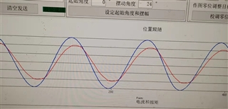
    2. I have done the experiment of tracking sine wave. I only use spintac-motion controller. The speed setting and acceleration setting in the controller are realized by seeking the first-order differential and second-order differential for the position reference. However, I find that the tracking effect of the system is very poor, and the actual position is always lower than the given position?

    Can you provide some ideas?

    Thank you very much!

  • No more good idea, just have to tune the control bandwidth and motion profile, and make sure than the inertia and friction are identified correctly.

    If you have to achieve a better performance, you may try use the InstaSPIN-motion based on position sensor.

  • Thanks for your reply!


    I still have the following questions:


    1. I have used a rotary transformer on my motor as rotor position feedback. I have modified the motor parameters and system parameters according to Lab5C to keep them consistent with our system, so there should be no problem in the identification of the moment of inertia and friction coefficient. I have adjusted the bandwidth of spintac-Motion controller according to the tutorial of lab13a, and the motor can maintain 0 speed very well, so I think there should be no problem with the bandwidth parameters.


    2. Do you think I should increase the bandwidth if I only use spintac-motion controller to control the motor? I have done experiments, increasing the bandwidth can improve the servo performance, but when the frequency of the target curve increases, increasing the bandwidth will lead to system instability, and I can solve this problem through the PID controller.


    3. I tried to generate the reference position sequence by MOVE suite, but the calculation time of MOVE suite between two points is too long. How to ensure that within a sine wave period, the reference position output by MOVE suite is also a full period sine wave?Do you have any suggestions? thank you!

    I hope you can answer my question. I really hope to improve my control performance through INSTASPIN suite. Thank you very much!

  • You may have a look at Chapter 11, 12 and 13 of the InstaSPIN-FOC and InstaSPIN-MOTION User's Guide https://www.ti.com/lit/spruhj1, which are all of the contents about the InstaSPIN-motion we can provide for you. You have to follow the InstaSPIN lab and user's guides to tune the related parameters that all we can have suggestions for InstaSPIN-MONTION on a detailed engineering project.