This thread has been locked.

If you have a related question, please click the "Ask a related question" button in the top right corner. The newly created question will be automatically linked to this question.

TMS320F28374D: PWM global load issue

Part Number: TMS320F28374D

Hi experts,

My customer encountered an issue about global load. Here are his settings:

1. EPWM1EPWM2EPWM7EPWM8 is one group;

2. Counter:  Up-Mode;

3.Enable the shadow mode of TBPRD CMPACMPB;

4. Enable global mode of TBPRD_TBPRDHRCMPA_CPMAHRCMPB_CMPBHRAQCTLA_AQCTLA2AQCTLB_AQCTLB2;

5. Global load in CNT=PRD;

6. Enable OSHTMODE of Global load;

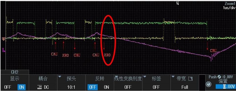
In his application, he need to change AQCTLA of EPWM7EPWM8, from ZRO↑, CAU↑, CBU↓ change to ZRO↓, CAU↑, CBU↓. But there randomly occurs when the ZRO should  be set low, but remains high, as follows:

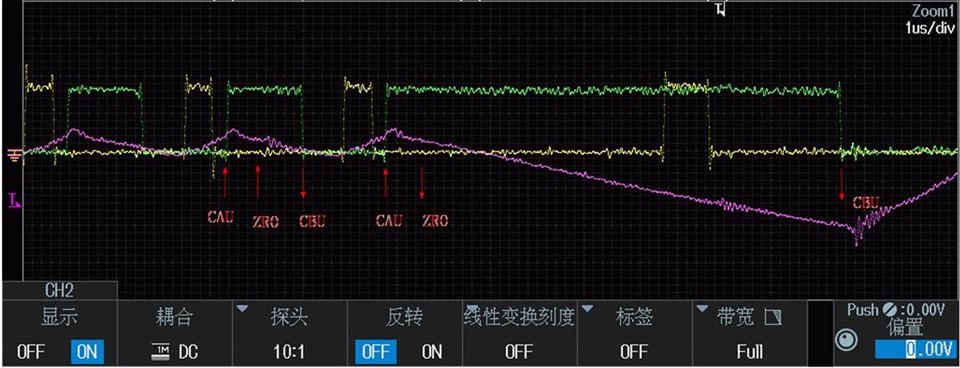
As shown in the figure above: At the second CNT=PRD, AQCTLx, TBPRD, CMPA, CMPB are updated. So at the second CNT=ZRO, It should be a pull-down drive, but the result is still keeping high. 

Please help on this issue, thank you!

  • Hi Angela,

    Thank you for your detailed question. Do you know if the OSHTLD bit within the GLDCTL2 register is being updated to cause the update?

    If using driverlib this would translate to the following function, EPWM_setGlobalLoadOneShotLatch()

    Similarly, the GLD bit of GLDCTL needs to be set to 1 in order to use the global load feature which is separate from items 4 and 6 above.

    This translates to EPWM_enableGlobalLoad() in driverlib.

    Also, can you please describe where the updates are being made? Timer ISR, ADC ISR?

    Best Regards,

    Marlyn

  • Hi Marlyn,

    The GLD bit has been set to 1. All the updates are in the timer interrupt.

  • Hi Angela,

    Is this issue only seen on EPWM7/8? and does it only occur on the next cycle following a one-shot load or does the AQCTLA action never update?

    Could you please provide some code so we can duplicate the code on our side?

    I did a short test with EPWM1/2 and the AQCTL settings are updated:

    //
    // Included Files
    //
    #include "F28x_Project.h"
    
    
    //
    // Globals
    //
    uint16_t EPwm1TimerIntCount;
    uint16_t EPwm2TimerIntCount;
    
    //
    // Function Prototypes
    //
    void InitEPwm1Example(void);
    void InitEPwm2Example(void);
    __interrupt void epwm1_isr(void);
    __interrupt void epwm2_isr(void);
    __interrupt void cpu_timer0_isr(void);
    
    //
    // Main
    //
    void main(void)
    {
    //
    // Step 1. Initialize System Control:
    // PLL, WatchDog, enable Peripheral Clocks
    // This example function is found in the F2837xD_SysCtrl.c file.
    //
        InitSysCtrl();
    
    //
    // Step 2. Initialize GPIO:
    // This example function is found in the F2837xD_Gpio.c file and
    // illustrates how to set the GPIO to its default state.
    //
    //    InitGpio();
    
    //
    // enable PWM1, PWM2
    //
        CpuSysRegs.PCLKCR2.bit.EPWM1=1;
        CpuSysRegs.PCLKCR2.bit.EPWM2=1;
    
    
    //
    // For this case just init GPIO pins for ePWM1, ePWM2, ePWM3
    // These functions are in the F2837xD_EPwm.c file
    //
        InitEPwm1Gpio();
        InitEPwm2Gpio();
    
    //
    // Step 3. Clear all interrupts and initialize PIE vector table:
    // Disable CPU interrupts
    //
        DINT;
    
    //
    // Initialize the PIE control registers to their default state.
    // The default state is all PIE interrupts disabled and flags
    // are cleared.
    // This function is found in the F2837xD_PieCtrl.c file.
    //
        InitPieCtrl();
    
    //
    // Disable CPU interrupts and clear all CPU interrupt flags:
    //
        IER = 0x0000;
        IFR = 0x0000;
    
    //
    // Initialize the PIE vector table with pointers to the shell Interrupt
    // Service Routines (ISR).
    // This will populate the entire table, even if the interrupt
    // is not used in this example.  This is useful for debug purposes.
    // The shell ISR routines are found in F2837xD_DefaultIsr.c.
    // This function is found in F2837xD_PieVect.c.
    //
        InitPieVectTable();
        InitCpuTimers();
    
    //
    // Interrupts that are used in this example are re-mapped to
    // ISR functions found within this file.
    //
        EALLOW; // This is needed to write to EALLOW protected registers
        PieVectTable.EPWM1_INT = &epwm1_isr;
        PieVectTable.EPWM2_INT = &epwm2_isr;
        PieVectTable.TIMER0_INT = &cpu_timer0_isr;
        EDIS;   // This is needed to disable write to EALLOW protected registers
    
    
    //
    // Configure CPU-Timer 0 to __interrupt every 500 milliseconds:
    // 60MHz CPU Freq, 50 millisecond Period (in uSeconds)
    //
        ConfigCpuTimer(&CpuTimer0, 60, 500000);
    
    //
    // Step 4. Initialize the Device Peripherals:
    //
        EALLOW;
        CpuSysRegs.PCLKCR0.bit.TBCLKSYNC =0;
        EDIS;
    
        InitEPwm1Example();
        InitEPwm2Example();
    
        EALLOW;
        CpuSysRegs.PCLKCR0.bit.TBCLKSYNC =1;
        EDIS;
    
    //
    // Start the timer
    //
        CpuTimer0Regs.TCR.all = 0x4001;
    
    //
    // Step 5. User specific code, enable interrupts:
    // Initialize counters:
    //
        EPwm1TimerIntCount = 0;
        EPwm2TimerIntCount = 0;
    
    //
    // Enable CPU INT3 which is connected to EPWM1-2 INT and INT1 for Timer 0
    //
        IER |= M_INT3;
        IER |= M_INT1;
    
    //
    // Enable EPWM INTn in the PIE
    //
        PieCtrlRegs.PIEIER3.bit.INTx1 = 1;
        PieCtrlRegs.PIEIER3.bit.INTx2 = 1;
        PieCtrlRegs.PIEIER1.bit.INTx7 = 1;
    
    //
    // Enable global Interrupts and higher priority real-time debug events:
    //
        EINT;  // Enable Global interrupt INTM
        ERTM;  // Enable Global realtime interrupt DBGM
    
    //
    // Step 6. IDLE loop. Just sit and loop forever (optional):
    //
        for(;;)
        {
            asm ("          NOP");
        }
    }
    
    
    //
    // cpu_timer0_isr - CPU Timer0 ISR
    //
    __interrupt void cpu_timer0_isr(void)
    {
       CpuTimer0.InterruptCount++;
    
       //
       // Update the AQCTL settings of EPWM1 and EPWM2
       //
       EPwm1Regs.AQCTLA.bit.ZRO = AQ_CLEAR;          // Clear PWM1A on Zero
       EPwm2Regs.AQCTLA.bit.ZRO = AQ_CLEAR;          // Clear PWM1A on Zero
    
       // EPWM1 and EPWM2 are linked so this will udpate both
       EALLOW;
       EPwm1Regs.GLDCTL2.bit.OSHTLD = 1;               // Enable re-load of Actions
       EDIS;
    
       //
       // Acknowledge this __interrupt to receive more __interrupts from group 1
       //
       PieCtrlRegs.PIEACK.all = PIEACK_GROUP1;
    }
    
    //
    // epwm1_isr - EPWM1 ISR
    //
    __interrupt void epwm1_isr(void)
    {
        EPwm1TimerIntCount++;
    
        //
        // Clear INT flag for this timer
        //
        EPwm1Regs.ETCLR.bit.INT = 1;
    
        //
        // Acknowledge this interrupt to receive more interrupts from group 3
        //
        PieCtrlRegs.PIEACK.all = PIEACK_GROUP3;
    }
    
    //
    // epwm2_isr - EPWM2 ISR
    //
    __interrupt void epwm2_isr(void)
    {
        EPwm2TimerIntCount++;
    
        //
        // Clear INT flag for this timer
        //
        EPwm2Regs.ETCLR.bit.INT = 1;
    
        //
        // Acknowledge this interrupt to receive more interrupts from group 3
        //
        PieCtrlRegs.PIEACK.all = PIEACK_GROUP3;
    }
    
    
    //
    // InitEPwm1Example - Initialize EPWM1 configuration
    //
    void InitEPwm1Example()
    {
    
        //
        // Global Loading Settings
        //
        EALLOW;
        EPwm1Regs.GLDCTL.bit.GLD = 1;               // Enable Global Shadow to Active Load
        EPwm1Regs.GLDCTL.bit.GLDMODE = 1;           // Load on Counter = PRD
        EPwm1Regs.GLDCTL.bit.OSHTMODE = 1;          // One-Shot mode is active
    
        //
        // Global Load Parameters
        //
        EPwm1Regs.GLDCFG.bit.AQCTLA_AQCTLA2 = 1;
        EPwm1Regs.GLDCFG.bit.AQCTLB_AQCTLB2 = 1;
        EPwm1Regs.GLDCFG.bit.TBPRD_TBPRDHR = 1;
        EPwm1Regs.GLDCFG.bit.CMPA_CMPAHR = 1;
        EPwm1Regs.GLDCFG.bit.CMPB_CMPBHR = 1;
        EDIS;
    
        EPwm1Regs.TBPRD = 6000;                       // Set timer period
        EPwm1Regs.TBPHS.bit.TBPHS = 0x0000;           // Phase is 0
        EPwm1Regs.TBCTR = 0x0000;                     // Clear counter
    
        //
        // Setup TBCLK
        //
        EPwm1Regs.TBCTL.bit.CTRMODE = TB_COUNT_UP;     // Count up
        EPwm1Regs.TBCTL.bit.PHSEN = TB_DISABLE;        // Disable phase loading
        EPwm1Regs.TBCTL.bit.HSPCLKDIV = TB_DIV4;       // Clock ratio to SYSCLKOUT
        EPwm1Regs.TBCTL.bit.CLKDIV = TB_DIV4;
    
        //
        // Setup compare
        //
        EPwm1Regs.CMPA.bit.CMPA = 5000;
        EPwm1Regs.CMPB.bit.CMPB = 1000;
    
        EPwm1Regs.CMPCTL.bit.SHDWAMODE = CC_SHADOW;    // Load registers every ZERO
        EPwm1Regs.CMPCTL.bit.SHDWBMODE = CC_SHADOW;
        EPwm1Regs.CMPCTL.bit.LOADAMODE = CC_CTR_ZERO;
        EPwm1Regs.CMPCTL.bit.LOADBMODE = CC_CTR_ZERO;
    
        //
        // Set actions
        //
        EPwm1Regs.AQCTLA.bit.CAU = AQ_SET;            // Set PWM1A on CAU
        EPwm1Regs.AQCTLA.bit.CBU = AQ_CLEAR;          // Clear PWM1A on CBU
        EPwm1Regs.AQCTLA.bit.ZRO = AQ_SET;            // Set PWM1A on Zero
    
        //
        // Interrupt
        //
        EPwm1Regs.ETSEL.bit.INTSEL = ET_CTR_ZERO;    // Select INT on Zero event
        EPwm1Regs.ETSEL.bit.INTEN = 1;               // Enable INT
        EPwm1Regs.ETPS.bit.INTPRD = ET_3RD;          // Generate INT on 3rd event
    
        EALLOW;
        EPwm1Regs.GLDCTL2.bit.OSHTLD = 1;           // Load shadow to active for initialization
        EDIS;
    }
    
    //
    // InitEPwm2Example - Initialize EPWM2 configuration
    //
    void InitEPwm2Example()
    {
    
        EPwm2Regs.TBPRD = 6000;                       // Set timer period
        EPwm2Regs.TBPHS.bit.TBPHS = 0x0000;           // Phase is 0
        EPwm2Regs.TBCTR = 0x0000;                     // Clear counter
    
        //
        // Setup TBCLK
        //
        EPwm2Regs.TBCTL.bit.CTRMODE = TB_COUNT_UP;     // Count up
        EPwm2Regs.TBCTL.bit.PHSEN = TB_DISABLE;        // Disable phase loading
        EPwm2Regs.TBCTL.bit.HSPCLKDIV = TB_DIV4;       // Clock ratio to SYSCLKOUT
        EPwm2Regs.TBCTL.bit.CLKDIV = TB_DIV4;          // Slow just to observe on
                                                       // the scope
    
        //
        // Setup compare
        //
        EPwm2Regs.CMPA.bit.CMPA = 5000;
        EPwm2Regs.CMPB.bit.CMPB = 1000;
    
        EPwm2Regs.CMPCTL.bit.SHDWAMODE = CC_SHADOW;    // Load registers every ZERO
        EPwm2Regs.CMPCTL.bit.SHDWBMODE = CC_SHADOW;
        EPwm2Regs.CMPCTL.bit.LOADAMODE = CC_CTR_ZERO;
        EPwm2Regs.CMPCTL.bit.LOADBMODE = CC_CTR_ZERO;
    
        //
        // Global Loading Settings
        //
        EALLOW;
        EPwm2Regs.GLDCTL.bit.GLD = 1;               // Enable Global Shadow to Active Load
        EPwm2Regs.GLDCTL.bit.GLDMODE = 1;           // Load on Counter = PRD
        EPwm2Regs.GLDCTL.bit.OSHTMODE = 1;          // One-Shot mode is active
    
        //
        // Global Load Parameters
        //
        EPwm2Regs.GLDCFG.bit.AQCTLA_AQCTLA2 = 1;
        EPwm2Regs.GLDCFG.bit.AQCTLB_AQCTLB2 = 1;
        EPwm2Regs.GLDCFG.bit.TBPRD_TBPRDHR = 1;
        EPwm2Regs.GLDCFG.bit.CMPA_CMPAHR = 1;
        EPwm2Regs.GLDCFG.bit.CMPB_CMPBHR = 1;
        EDIS;
    
        //
        // Set actions
        //
        EPwm2Regs.AQCTLA.bit.CAU = AQ_SET;            // Set PWM2A on CAU
        EPwm2Regs.AQCTLA.bit.CBU = AQ_CLEAR;          // Clear PWM2A on CBU
        EPwm2Regs.AQCTLA.bit.ZRO = AQ_SET;            // Set PWM2A on Zero
    
        //
        // Interrupt
        //
        EPwm2Regs.ETSEL.bit.INTSEL = ET_CTR_ZERO;     // Select INT on Zero event
        EPwm2Regs.ETSEL.bit.INTEN = 1;                // Enable INT
        EPwm2Regs.ETPS.bit.INTPRD = ET_3RD;           // Generate INT on 3rd event
    
    
        EALLOW;
        EPwm2Regs.GLDCTL2.bit.OSHTLD = 1;           // Load shadow to active for initialization
        EDIS;
    
        //
        // Linking
        //
        EPwm2Regs.EPWMXLINK.bit.GLDCTL2LINK = 0;   // Link to ePWM1
        EPwm2Regs.EPWMXLINK.bit.CMPALINK = 0;      // Link to ePWM1
        EPwm2Regs.EPWMXLINK.bit.CMPBLINK = 0;      // Link to ePWM1
        EPwm2Regs.EPWMXLINK.bit.TBPRDLINK = 0;     // Link to ePWM1
    }

    Best Regards,

    Marlyn

  • Hi Marlyn,

    Not only on EPWM7/8, it happens and occurs at an intermittent interval as long as the AQCTLA of any EPWM module is changed in the interrupt. It looks like that AQCTLA is not updated at some time, and it is sporadic, the AQCTLA is updated normally most of the time.

    I am sorry that customer can not provide us source code. But they can provide deep information or further test if needed.

  • Are all other items in the global load being updated as needed? Can you check to see how the customer is confirming that the AQCTLA is not being updated?

  • Hi Nima,

    The yellow wave is  EPWM7_A; the green wave is EPWM8_A. EPWM7_a and EPWM8_a are upper and lower bridge arm drives with 150ns dead zone time. EPWM7.EPWM8 are all up mode. 

    EPWM7: ZRO CAUCBU↓,EPWM7_CMPB- EPWM7_CMPA = Ton.

    EPWM8: If CMPB > TBPRDZRO CAUCBU↓,EPWM8_CMPB = EPWM8_CMPB TBPRDPWM8_CMPA- EPWM8_CMPB = Toff

                   If CMPB TBPRD, ZRO CAUCBU↓,EPWM8_CMPB = EPWM8_CMPB 1, EPWM8_CMPB- EPWM8_CMPA = Toff

    All the actions are updated every 40k. If the CMPA and CMPB values are incorrect, then it should last 25us (40k). As shown in Figure 1 below, if the update is successful, then the second ZRO should be set low and pass-through will not occur. It is possible that the second time ZRO should still be set high (the update is not valid) and causes pass-through. The subsequent waveform is then normal (Figure 2)

    Figure1:

    Figure2:
  • Can you capture what the CMPA/CMPB values are when the error occurs? 

    PRD is the same at all times.

    Nima

  • Hi Nima,

    As the switching frequency is too high and also the issue is occasional, it is very difficult to capture the CMPA and CMPB. Maybe we have to use another way to find the root cause.

  • The method to capture the values are:

    1. Set up a buffer to capture the CMPA/CMPB, Actions, etc. (20 or so deep)

    2. Set up an ECAP to capture the HIGH time of the EPWM signal, and when the extremely long pulse is detected, generate and ESTOP0 and read the values in the captured buffer.

    Nima