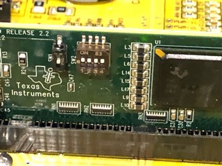
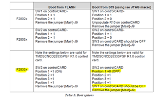
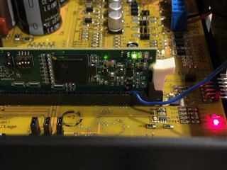
Part Number: TMDSHVMTRPFCKIT
Hello,
We got the TMDSHVMTRPFCKIT for us to use with 3 phase motor control. The kit was working ok and I was able to get the motor to rotate at a desired using the Piccolo card 28035.
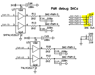
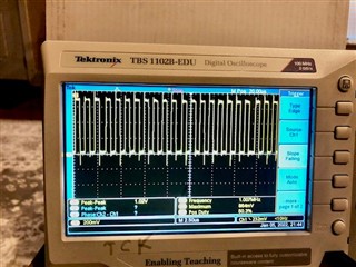
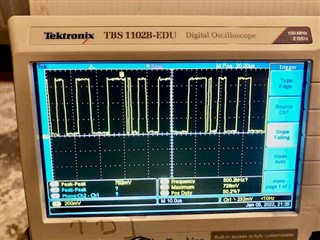
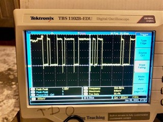
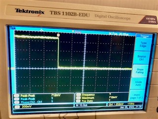
One time after I used the oscilloscope to measure one of the 4 D/A pins, the Piccolo card stopped working and I am no longer able to flash software or communicate with it.
I replaced the 28035 by the Delfino 28335. I can see the main board is powered and the control board is also powered but I am not able to download code to the card.
I believe communication between laptop and the FTDI hardware works, but probably the FTDI is not able to flash the control card.
I was developing code using embedded coder and flashing from Simulink.
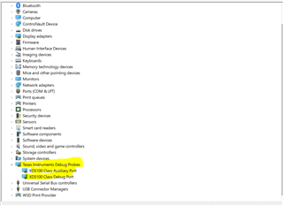
- Testing the connection:
C:\TI\ccs1020\ccs\ccs_base\common\uscif>xds100serial.exe
Scanning for XDS100 emulators...
VID/PID Type Serial # Description
0403/a6d0 XDS100v1/v2 TI3GQTWK Texas Instruments XDS100+RS232 V1.0
- When trying to flash code on the control card:
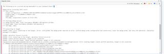
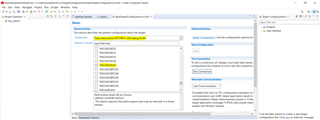
- Testing Connection using code composer studio
[Start: Texas Instruments XDS100v1 USB Debug Probe_0]
Execute the command:
%ccs_base%/common/uscif/dbgjtag -f %boarddatafile% -rv -o -F inform,logfile=yes -S pathlength -S integrity
[Result]
-----[Print the board config pathname(s)]------------------------------------
C:\Users\younesd\AppData\Local\TEXASI~1\
CCS\ccs1020\0\0\BrdDat\testBoard.dat
-----[Print the reset-command software log-file]-----------------------------
This utility has selected a 100- or 510-class product.
This utility will load the adapter 'jioserdesusb.dll'.
The library build date was 'Jan 1 2021'.
The library build time was '11:25:57'.
The library package version is '9.3.0.00032'.
The library component version is '35.35.0.0'.
The controller does not use a programmable FPGA.
The controller has a version number of '4' (0x00000004).
The controller has an insertion length of '0' (0x00000000).
This utility will attempt to reset the controller.
This utility has successfully reset the controller.
-----[Print the reset-command hardware log-file]-----------------------------
The scan-path will be reset by toggling the JTAG TRST signal.
The controller is the FTDI FT2232 with USB interface.
The link from controller to target is direct (without cable).
The software is configured for FTDI FT2232 features.
The controller cannot monitor the value on the EMU[0] pin.
The controller cannot monitor the value on the EMU[1] pin.
The controller cannot control the timing on output pins.
The controller cannot control the timing on input pins.
The scan-path link-delay has been set to exactly '0' (0x0000).
-----[The log-file for the JTAG TCLK output generated from the PLL]----------
There is no hardware for programming the JTAG TCLK frequency.
-----[Measure the source and frequency of the final JTAG TCLKR input]--------
There is no hardware for measuring the JTAG TCLK frequency.
-----[Perform the standard path-length test on the JTAG IR and DR]-----------
This path-length test uses blocks of 64 32-bit words.
The test for the JTAG IR instruction path-length failed.
The JTAG IR instruction scan-path is stuck-at-ones.
The test for the JTAG DR bypass path-length failed.
The JTAG DR bypass scan-path is stuck-at-ones.
-----[Perform the Integrity scan-test on the JTAG IR]------------------------
This test will use blocks of 64 32-bit words.
This test will be applied just once.
Do a test using 0xFFFFFFFF.
Scan tests: 1, skipped: 0, failed: 0
Do a test using 0x00000000.
Test 2 Word 0: scanned out 0x00000000 and scanned in 0xFFFFFFFF.
Test 2 Word 1: scanned out 0x00000000 and scanned in 0xFFFFFFFF.
Test 2 Word 2: scanned out 0x00000000 and scanned in 0xFFFFFFFF.
Test 2 Word 3: scanned out 0x00000000 and scanned in 0xFFFFFFFF.
Test 2 Word 4: scanned out 0x00000000 and scanned in 0xFFFFFFFF.
Test 2 Word 5: scanned out 0x00000000 and scanned in 0xFFFFFFFF.
Test 2 Word 6: scanned out 0x00000000 and scanned in 0xFFFFFFFF.
Test 2 Word 7: scanned out 0x00000000 and scanned in 0xFFFFFFFF.
The details of the first 8 errors have been provided.
The utility will now report only the count of failed tests.
Scan tests: 2, skipped: 0, failed: 1
Do a test using 0xFE03E0E2.
Scan tests: 3, skipped: 0, failed: 2
Do a test using 0x01FC1F1D.
Scan tests: 4, skipped: 0, failed: 3
Do a test using 0x5533CCAA.
Scan tests: 5, skipped: 0, failed: 4
Do a test using 0xAACC3355.
Scan tests: 6, skipped: 0, failed: 5
Some of the values were corrupted - 83.3 percent.
The JTAG IR Integrity scan-test has failed.
-----[Perform the Integrity scan-test on the JTAG DR]------------------------
This test will use blocks of 64 32-bit words.
This test will be applied just once.
Do a test using 0xFFFFFFFF.
Scan tests: 1, skipped: 0, failed: 0
Do a test using 0x00000000.
Test 2 Word 0: scanned out 0x00000000 and scanned in 0xFFFFFFFF.
Test 2 Word 1: scanned out 0x00000000 and scanned in 0xFFFFFFFF.
Test 2 Word 2: scanned out 0x00000000 and scanned in 0xFFFFFFFF.
Test 2 Word 3: scanned out 0x00000000 and scanned in 0xFFFFFFFF.
Test 2 Word 4: scanned out 0x00000000 and scanned in 0xFFFFFFFF.
Test 2 Word 5: scanned out 0x00000000 and scanned in 0xFFFFFFFF.
Test 2 Word 6: scanned out 0x00000000 and scanned in 0xFFFFFFFF.
Test 2 Word 7: scanned out 0x00000000 and scanned in 0xFFFFFFFF.
The details of the first 8 errors have been provided.
The utility will now report only the count of failed tests.
Scan tests: 2, skipped: 0, failed: 1
Do a test using 0xFE03E0E2.
Scan tests: 3, skipped: 0, failed: 2
Do a test using 0x01FC1F1D.
Scan tests: 4, skipped: 0, failed: 3
Do a test using 0x5533CCAA.
Scan tests: 5, skipped: 0, failed: 4
Do a test using 0xAACC3355.
Scan tests: 6, skipped: 0, failed: 5
Some of the values were corrupted - 83.3 percent.
The JTAG DR Integrity scan-test has failed.
[End: Texas Instruments XDS100v1 USB Debug Probe_0]
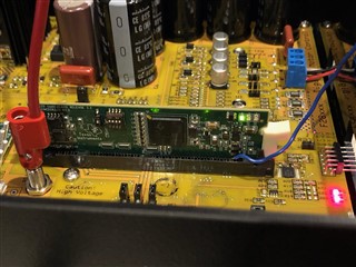
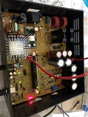
- Image of the board used
Could you please help me on this.
Thank you