This thread has been locked.

If you have a related question, please click the "Ask a related question" button in the top right corner. The newly created question will be automatically linked to this question.

TMDSCNCD28379D: PCB design question

Part Number: TMDSCNCD28379D
Other Parts Discussed in Thread: C2000WARE

Hi Team,

The customer get the gerber file of TMDSCNCD28379D Daughter card | TI.com. They need some detail of the PCB design for reference.

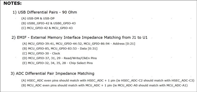
Can you please kindly help provide the detailed illustration about below each layer impedance requirement with red highlighted, such as each number meaning and why does this board need them? Thank you.

Best regards,

Mike

  • Please see the notes on the first page of the schematic.

    xxSE means single ended, or to ground. xxDIF means differential or between two signals. The number in front represents the resistance.

    Regards,
    Cody 

  • Hi Cody,

    Thanks…so you mean the impedance of the traces listed in the notes are required as the statement, how about other traces not listed in the notes?

    Best regards,

    Mike

  • Mike,

    the layout is provided. You will need to parse through the information. 

    "IMPEDANCE - 5.3 - 50SE, 5/6 = 90DIF, 4.3/4.7 - 100DIF", taken from the top layer.

    • "5.3 - 50SE" means that 5.3mil traces should have 50 ohms to ground
    • "5/6 = 90DIF" means that 6 or 5 mil traces should have 90 ohms differential
    • etc.

    Each of these traces have a different purpose, but all of them are intended to get better signal integrity. Off of the top of my head I expect the 100ohms to be used for differential analog signals, 90Ohms for the USB differential signals, and i'm not sure what the 50Ohm traces are used for. But feel free to go and explore the layout and find out. 

    The files can be found in C2000Ware.C:\ti\c2000\C2000Ware_3_04_00_00\boards\controlCARDs\TMDSCNCD28379D 

    Regards,
    Cody 

  • Hi Cody,

    Get it, thanks for your support.

    Best regards,

    Mike