Part Number: TMS320F28386S
Other Parts Discussed in Thread: SYSCONFIG
Hi,
The peripherals on the C2000 devices has gotten so complex that it is sometimes hard to understand how to make the best of it :-)
I have 6 analog signals.
3 connected to ADCA and 3 connected to ADCB
I need to sample all 6 signals at the same time, or as close to each other as possible.
I have configured as fallows:
SOC0 -> ADCA ch2, trig EPWM1
SOC1 -> ADCA ch3, trig EPWM1
SOC2 -> ADCA ch4, trig EPWM1
SOC0 -> ADCB ch2, trig EPWM1
SOC1 -> ADCB ch3, trig EPWM1
SOC2 -> ADCB ch4, trig EPWM1
ADCA interrupt.
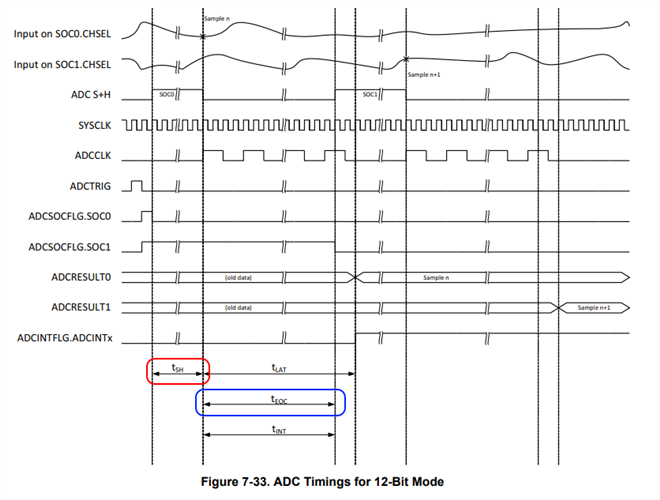
acquisition time is set to 60 clocks. 60 * 5ns = 300ns.
I have 2 questions:
1: what is happening in this current configuration?
I was guessing that on EPWM1 trigger, a conversion will start on all channels?
Are all 6 channels sampled every EPWM event?
Do I need to use Burst mode to make this work properly?
2: when profiling on the scope, the time between EPWM1 trigger and ADC ISR is 1.5us
that is 5 * 300ns conversion time.
I don't understand this result.
I would expect, (if ADC A and B are sampling simultaneously) that the conversion time will be 3 samples * 300ns.
I would love some guidance on the best configuration.
Thanks!
See configuration from sysConfig
void ADC_init(){
//M_PAN_ADCA initialization
// ADC Initialization: Write ADC configurations and power up the ADC
// Configures the analog-to-digital converter module prescaler.
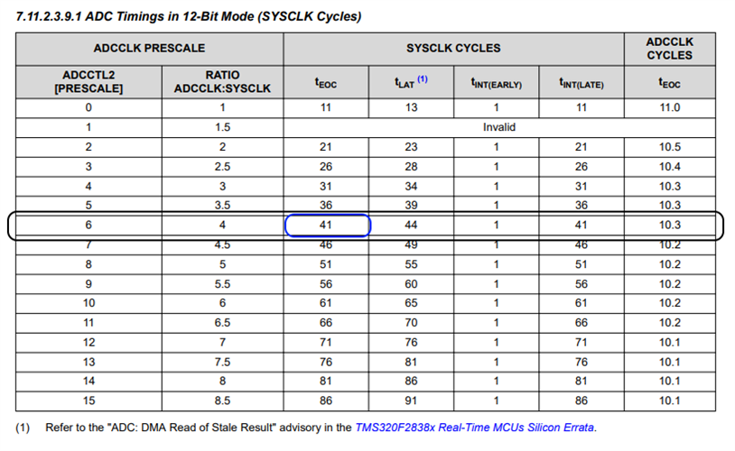
ADC_setPrescaler(M_PAN_ADCA_BASE, ADC_CLK_DIV_4_0);
// Configures the analog-to-digital converter resolution and signal mode.
ADC_setMode(M_PAN_ADCA_BASE, ADC_RESOLUTION_12BIT, ADC_MODE_SINGLE_ENDED);
// Sets the timing of the end-of-conversion pulse
ADC_setInterruptPulseMode(M_PAN_ADCA_BASE, ADC_PULSE_END_OF_CONV);
// Powers up the analog-to-digital converter core.
ADC_enableConverter(M_PAN_ADCA_BASE);
// Delay for 1ms to allow ADC time to power up
DEVICE_DELAY_US(500);
// SOC Configuration: Setup ADC EPWM channel and trigger settings
// Disables SOC burst mode.
ADC_disableBurstMode(M_PAN_ADCA_BASE);
// Sets the priority mode of the SOCs.
ADC_setSOCPriority(M_PAN_ADCA_BASE, ADC_PRI_ALL_ROUND_ROBIN);
// Start of Conversion 0 Configuration
// Configures a start-of-conversion (SOC) in the ADC and its interrupt SOC trigger.
// SOC number : 0
// Trigger : ADC_TRIGGER_EPWM1_SOCA
// Channel : ADC_CH_ADCIN2
// Sample Window : 60 SYSCLK cycles
// Interrupt Trigger: ADC_INT_SOC_TRIGGER_NONE
ADC_setupSOC(M_PAN_ADCA_BASE, ADC_SOC_NUMBER0, ADC_TRIGGER_EPWM1_SOCA, ADC_CH_ADCIN2, 60U);
ADC_setInterruptSOCTrigger(M_PAN_ADCA_BASE, ADC_SOC_NUMBER0, ADC_INT_SOC_TRIGGER_NONE);
// Start of Conversion 1 Configuration
// Configures a start-of-conversion (SOC) in the ADC and its interrupt SOC trigger.
// SOC number : 1
// Trigger : ADC_TRIGGER_EPWM1_SOCA
// Channel : ADC_CH_ADCIN3
// Sample Window : 60 SYSCLK cycles
// Interrupt Trigger: ADC_INT_SOC_TRIGGER_NONE
ADC_setupSOC(M_PAN_ADCA_BASE, ADC_SOC_NUMBER1, ADC_TRIGGER_EPWM1_SOCA, ADC_CH_ADCIN3, 60U);
ADC_setInterruptSOCTrigger(M_PAN_ADCA_BASE, ADC_SOC_NUMBER1, ADC_INT_SOC_TRIGGER_NONE);
// Start of Conversion 2 Configuration
// Configures a start-of-conversion (SOC) in the ADC and its interrupt SOC trigger.
// SOC number : 2
// Trigger : ADC_TRIGGER_EPWM1_SOCA
// Channel : ADC_CH_ADCIN4
// Sample Window : 60 SYSCLK cycles
// Interrupt Trigger: ADC_INT_SOC_TRIGGER_NONE
ADC_setupSOC(M_PAN_ADCA_BASE, ADC_SOC_NUMBER2, ADC_TRIGGER_EPWM1_SOCA, ADC_CH_ADCIN4, 60U);
ADC_setInterruptSOCTrigger(M_PAN_ADCA_BASE, ADC_SOC_NUMBER2, ADC_INT_SOC_TRIGGER_NONE);
// ADC Interrupt 1 Configuration
// SOC/EOC number : 2
// Interrupt Source: enabled
// Continuous Mode : disabled
ADC_setInterruptSource(M_PAN_ADCA_BASE, ADC_INT_NUMBER1, ADC_SOC_NUMBER2);
ADC_enableInterrupt(M_PAN_ADCA_BASE, ADC_INT_NUMBER1);
ADC_clearInterruptStatus(M_PAN_ADCA_BASE, ADC_INT_NUMBER1);
ADC_disableContinuousMode(M_PAN_ADCA_BASE, ADC_INT_NUMBER1);
// PPB Configuration: Configure high and low limits detection for ADCPPB
// Post Processing Block 1 Configuration
// Configures a post-processing block (PPB) in the ADC.
// PPB Number : 1
// SOC/EOC number : 0
// Calibration Offset : 0
// Reference Offset : 0
// Two's Complement : Disabled
// Trip High Limit : 0
// Trip Low Limit : 0
// Clear PPB Event Flags : Disabled
ADC_setupPPB(M_PAN_ADCA_BASE, ADC_PPB_NUMBER1, ADC_SOC_NUMBER0);
ADC_disablePPBEvent(M_PAN_ADCA_BASE, ADC_PPB_NUMBER1, (ADC_EVT_TRIPHI | ADC_EVT_TRIPLO | ADC_EVT_ZERO));
ADC_disablePPBEventInterrupt(M_PAN_ADCA_BASE, ADC_PPB_NUMBER1, (ADC_EVT_TRIPHI | ADC_EVT_TRIPLO | ADC_EVT_ZERO));
ADC_setPPBCalibrationOffset(M_PAN_ADCA_BASE, ADC_PPB_NUMBER1, 0);
ADC_setPPBReferenceOffset(M_PAN_ADCA_BASE, ADC_PPB_NUMBER1, 0);
ADC_disablePPBTwosComplement(M_PAN_ADCA_BASE, ADC_PPB_NUMBER1);
ADC_setPPBTripLimits(M_PAN_ADCA_BASE, ADC_PPB_NUMBER1, 0, 0);
ADC_disablePPBEventCBCClear(M_PAN_ADCA_BASE, ADC_PPB_NUMBER1);
// Post Processing Block 2 Configuration
// Configures a post-processing block (PPB) in the ADC.
// PPB Number : 2
// SOC/EOC number : 1
// Calibration Offset : 0
// Reference Offset : 0
// Two's Complement : Disabled
// Trip High Limit : 0
// Trip Low Limit : 0
// Clear PPB Event Flags : Disabled
ADC_setupPPB(M_PAN_ADCA_BASE, ADC_PPB_NUMBER2, ADC_SOC_NUMBER1);
ADC_disablePPBEvent(M_PAN_ADCA_BASE, ADC_PPB_NUMBER2, (ADC_EVT_TRIPHI | ADC_EVT_TRIPLO | ADC_EVT_ZERO));
ADC_disablePPBEventInterrupt(M_PAN_ADCA_BASE, ADC_PPB_NUMBER2, (ADC_EVT_TRIPHI | ADC_EVT_TRIPLO | ADC_EVT_ZERO));
ADC_setPPBCalibrationOffset(M_PAN_ADCA_BASE, ADC_PPB_NUMBER2, 0);
ADC_setPPBReferenceOffset(M_PAN_ADCA_BASE, ADC_PPB_NUMBER2, 0);
ADC_disablePPBTwosComplement(M_PAN_ADCA_BASE, ADC_PPB_NUMBER2);
ADC_setPPBTripLimits(M_PAN_ADCA_BASE, ADC_PPB_NUMBER2, 0, 0);
ADC_disablePPBEventCBCClear(M_PAN_ADCA_BASE, ADC_PPB_NUMBER2);
// Post Processing Block 3 Configuration
// Configures a post-processing block (PPB) in the ADC.
// PPB Number : 3
// SOC/EOC number : 2
// Calibration Offset : 0
// Reference Offset : 0
// Two's Complement : Disabled
// Trip High Limit : 0
// Trip Low Limit : 0
// Clear PPB Event Flags : Disabled
ADC_setupPPB(M_PAN_ADCA_BASE, ADC_PPB_NUMBER3, ADC_SOC_NUMBER2);
ADC_disablePPBEvent(M_PAN_ADCA_BASE, ADC_PPB_NUMBER3, (ADC_EVT_TRIPHI | ADC_EVT_TRIPLO | ADC_EVT_ZERO));
ADC_disablePPBEventInterrupt(M_PAN_ADCA_BASE, ADC_PPB_NUMBER3, (ADC_EVT_TRIPHI | ADC_EVT_TRIPLO | ADC_EVT_ZERO));
ADC_setPPBCalibrationOffset(M_PAN_ADCA_BASE, ADC_PPB_NUMBER3, 0);
ADC_setPPBReferenceOffset(M_PAN_ADCA_BASE, ADC_PPB_NUMBER3, 0);
ADC_disablePPBTwosComplement(M_PAN_ADCA_BASE, ADC_PPB_NUMBER3);
ADC_setPPBTripLimits(M_PAN_ADCA_BASE, ADC_PPB_NUMBER3, 0, 0);
ADC_disablePPBEventCBCClear(M_PAN_ADCA_BASE, ADC_PPB_NUMBER3);
//M_TILT_ADCB initialization
// ADC Initialization: Write ADC configurations and power up the ADC
// Configures the analog-to-digital converter module prescaler.
ADC_setPrescaler(M_TILT_ADCB_BASE, ADC_CLK_DIV_4_0);
// Configures the analog-to-digital converter resolution and signal mode.
ADC_setMode(M_TILT_ADCB_BASE, ADC_RESOLUTION_12BIT, ADC_MODE_SINGLE_ENDED);
// Sets the timing of the end-of-conversion pulse
ADC_setInterruptPulseMode(M_TILT_ADCB_BASE, ADC_PULSE_END_OF_CONV);
// Powers up the analog-to-digital converter core.
ADC_enableConverter(M_TILT_ADCB_BASE);
// Delay for 1ms to allow ADC time to power up
DEVICE_DELAY_US(500);
// SOC Configuration: Setup ADC EPWM channel and trigger settings
// Disables SOC burst mode.
ADC_disableBurstMode(M_TILT_ADCB_BASE);
// Sets the priority mode of the SOCs.
ADC_setSOCPriority(M_TILT_ADCB_BASE, ADC_PRI_ALL_ROUND_ROBIN);
// Start of Conversion 0 Configuration
// Configures a start-of-conversion (SOC) in the ADC and its interrupt SOC trigger.
// SOC number : 0
// Trigger : ADC_TRIGGER_EPWM1_SOCA
// Channel : ADC_CH_ADCIN2
// Sample Window : 60 SYSCLK cycles
// Interrupt Trigger: ADC_INT_SOC_TRIGGER_NONE
ADC_setupSOC(M_TILT_ADCB_BASE, ADC_SOC_NUMBER0, ADC_TRIGGER_EPWM1_SOCA, ADC_CH_ADCIN2, 60U);
ADC_setInterruptSOCTrigger(M_TILT_ADCB_BASE, ADC_SOC_NUMBER0, ADC_INT_SOC_TRIGGER_NONE);
// Start of Conversion 1 Configuration
// Configures a start-of-conversion (SOC) in the ADC and its interrupt SOC trigger.
// SOC number : 1
// Trigger : ADC_TRIGGER_EPWM1_SOCA
// Channel : ADC_CH_ADCIN3
// Sample Window : 60 SYSCLK cycles
// Interrupt Trigger: ADC_INT_SOC_TRIGGER_NONE
ADC_setupSOC(M_TILT_ADCB_BASE, ADC_SOC_NUMBER1, ADC_TRIGGER_EPWM1_SOCA, ADC_CH_ADCIN3, 60U);
ADC_setInterruptSOCTrigger(M_TILT_ADCB_BASE, ADC_SOC_NUMBER1, ADC_INT_SOC_TRIGGER_NONE);
// Start of Conversion 2 Configuration
// Configures a start-of-conversion (SOC) in the ADC and its interrupt SOC trigger.
// SOC number : 2
// Trigger : ADC_TRIGGER_EPWM1_SOCA
// Channel : ADC_CH_ADCIN4
// Sample Window : 60 SYSCLK cycles
// Interrupt Trigger: ADC_INT_SOC_TRIGGER_NONE
ADC_setupSOC(M_TILT_ADCB_BASE, ADC_SOC_NUMBER2, ADC_TRIGGER_EPWM1_SOCA, ADC_CH_ADCIN4, 60U);
ADC_setInterruptSOCTrigger(M_TILT_ADCB_BASE, ADC_SOC_NUMBER2, ADC_INT_SOC_TRIGGER_NONE);
// PPB Configuration: Configure high and low limits detection for ADCPPB
// Post Processing Block 1 Configuration
// Configures a post-processing block (PPB) in the ADC.
// PPB Number : 1
// SOC/EOC number : 0
// Calibration Offset : 0
// Reference Offset : 0
// Two's Complement : Disabled
// Trip High Limit : 0
// Trip Low Limit : 0
// Clear PPB Event Flags : Disabled
ADC_setupPPB(M_TILT_ADCB_BASE, ADC_PPB_NUMBER1, ADC_SOC_NUMBER0);
ADC_disablePPBEvent(M_TILT_ADCB_BASE, ADC_PPB_NUMBER1, (ADC_EVT_TRIPHI | ADC_EVT_TRIPLO | ADC_EVT_ZERO));
ADC_disablePPBEventInterrupt(M_TILT_ADCB_BASE, ADC_PPB_NUMBER1, (ADC_EVT_TRIPHI | ADC_EVT_TRIPLO | ADC_EVT_ZERO));
ADC_setPPBCalibrationOffset(M_TILT_ADCB_BASE, ADC_PPB_NUMBER1, 0);
ADC_setPPBReferenceOffset(M_TILT_ADCB_BASE, ADC_PPB_NUMBER1, 0);
ADC_disablePPBTwosComplement(M_TILT_ADCB_BASE, ADC_PPB_NUMBER1);
ADC_setPPBTripLimits(M_TILT_ADCB_BASE, ADC_PPB_NUMBER1, 0, 0);
ADC_disablePPBEventCBCClear(M_TILT_ADCB_BASE, ADC_PPB_NUMBER1);
// Post Processing Block 2 Configuration
// Configures a post-processing block (PPB) in the ADC.
// PPB Number : 2
// SOC/EOC number : 1
// Calibration Offset : 0
// Reference Offset : 0
// Two's Complement : Disabled
// Trip High Limit : 0
// Trip Low Limit : 0
// Clear PPB Event Flags : Disabled
ADC_setupPPB(M_TILT_ADCB_BASE, ADC_PPB_NUMBER2, ADC_SOC_NUMBER1);
ADC_disablePPBEvent(M_TILT_ADCB_BASE, ADC_PPB_NUMBER2, (ADC_EVT_TRIPHI | ADC_EVT_TRIPLO | ADC_EVT_ZERO));
ADC_disablePPBEventInterrupt(M_TILT_ADCB_BASE, ADC_PPB_NUMBER2, (ADC_EVT_TRIPHI | ADC_EVT_TRIPLO | ADC_EVT_ZERO));
ADC_setPPBCalibrationOffset(M_TILT_ADCB_BASE, ADC_PPB_NUMBER2, 0);
ADC_setPPBReferenceOffset(M_TILT_ADCB_BASE, ADC_PPB_NUMBER2, 0);
ADC_disablePPBTwosComplement(M_TILT_ADCB_BASE, ADC_PPB_NUMBER2);
ADC_setPPBTripLimits(M_TILT_ADCB_BASE, ADC_PPB_NUMBER2, 0, 0);
ADC_disablePPBEventCBCClear(M_TILT_ADCB_BASE, ADC_PPB_NUMBER2);
// Post Processing Block 3 Configuration
// Configures a post-processing block (PPB) in the ADC.
// PPB Number : 3
// SOC/EOC number : 2
// Calibration Offset : 0
// Reference Offset : 0
// Two's Complement : Disabled
// Trip High Limit : 0
// Trip Low Limit : 0
// Clear PPB Event Flags : Disabled
ADC_setupPPB(M_TILT_ADCB_BASE, ADC_PPB_NUMBER3, ADC_SOC_NUMBER2);
ADC_disablePPBEvent(M_TILT_ADCB_BASE, ADC_PPB_NUMBER3, (ADC_EVT_TRIPHI | ADC_EVT_TRIPLO | ADC_EVT_ZERO));
ADC_disablePPBEventInterrupt(M_TILT_ADCB_BASE, ADC_PPB_NUMBER3, (ADC_EVT_TRIPHI | ADC_EVT_TRIPLO | ADC_EVT_ZERO));
ADC_setPPBCalibrationOffset(M_TILT_ADCB_BASE, ADC_PPB_NUMBER3, 0);
ADC_setPPBReferenceOffset(M_TILT_ADCB_BASE, ADC_PPB_NUMBER3, 0);
ADC_disablePPBTwosComplement(M_TILT_ADCB_BASE, ADC_PPB_NUMBER3);
ADC_setPPBTripLimits(M_TILT_ADCB_BASE, ADC_PPB_NUMBER3, 0, 0);
ADC_disablePPBEventCBCClear(M_TILT_ADCB_BASE, ADC_PPB_NUMBER3);
}
void INTERRUPT_init(){
// Interrupt Setings for INT_M_PAN_ADCA_1
Interrupt_register(INT_M_PAN_ADCA_1, &INT_M_PAN_ADCA_1_ISR);
Interrupt_enable(INT_M_PAN_ADCA_1);
}