Part Number: TMS320F28379D
Other Parts Discussed in Thread: TMP1075, TMP175
Hello,
I've been banging my head against the wall of getting the I2C to play properly with a tmp1075. I started with the TI example i2C_ex5_master_slave_interrupt and have developed the following code, which works after a fashion:
//#############################################################################
//
// FILE: i2c_TMP1075.c
//
// TITLE: I2C set up and receive temperature values from the TMP1075/TMP175 device
//
//! Uses driverib functions and is very loosely based on TI demo code i2c_ex5_master_slave_interrupt
//!
//! This program uses the I2CA modules for achieving external
//! data from TMP1075. The I2CA RX FIFO is used along with
//! interrupts. It works, but is in need of further work.
//!
//! Use of device delay functions not compatible with real-time operation.....
//!
//! The device is initially configured to receive the correct temperature values
//! Timing and sequencing needs properly sorting as currently delays are in-line in the code to ensurer the I2C has time to send
//! and receive the values, the chip has a temperature conversion time of approx. 220ms and currently if the delay is set to < 30ms
//! the device seems to lock up, the datasheet specifies a timeout of 20ms or so which is probably what is being seen here, so the
//! stored temperature value can be read at approx. 1/30ms but is only updated internally at 1/220ms
//!
//! There must be some better I2C handshaking that can be used, but the correct methodology has been elusive so far.
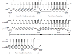
//! Sequence for reading temp is to transmit a pointer code of 00 , then switch to receive mode and trigger a start after
//! which the temp sensor will send data which triggers the interrupt
//! suggest this code needs to be embedded with a timer to trigger the correct I2C sequence and allow the time for the device to be ready to respond
//#############################################################################
// For hardware testing only
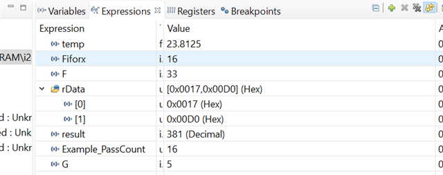
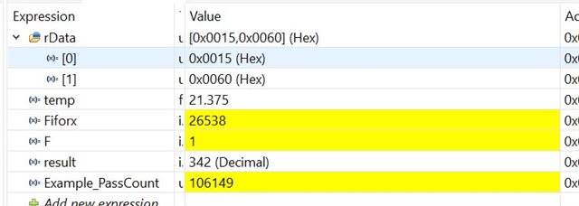
// watch variables rData, temp, fiforx, F, result, Example_Passcount
//Note, example_PassCount should be twice the rate of fiforx if this is working correctly but is four times the rate, not clear why....
// $
//#############################################################################
//
// Included Files
//
#include "driverlib.h"
#include "device.h"
//
// Defines
//
#define SLAVE_ADDRESS 0x48
#define POINTER_TEMP 0x00
#define POINTER_CONFIG 0x01
#define POINTER_TLOW 0x02
#define POINTER_THIGH 0x03
//TMP175 set up configuration:
#define TMP175_CONFIG 0x68
//D7- One shot - 0 - continuous conversion.
//D6,D5 - REsolution - Full 12 bit resolution 11 (220ms conversion time)
//D4,D3 - Noise filter - 2 consecutive faults for trip 01
//D2 - Polatiry - active low 0
//D1 - TM - comparator mode 0
//D0 - SD - continuous conversion 0
#define TMP175_TLOW 0x68
#define TMP175_THIGH 0x68
//
// Globals
//
uint16_t rData[2] = {0,0}; // Receive data buffer
uint16_t rDataPoint = 0; // To keep track of where we are in the
// data stream to check received data
int result = 0; //temp result
float temp = 0; //converted result
int F = 0; //test value
int Fiforx = 0;
//
// Function Prototypes
//
void initI2CFIFO(void);
void initTMP1075(void);
__interrupt void i2cFIFOISR(void);
//
// Main
//
void main(void)
{
uint16_t i;
//
// Initialize device clock and peripherals
//
Device_init();
//
// Disable pin locks and enable internal pullups.
//
Device_initGPIO();
//
// Initialize GPIOs 91 and 92 for use as SDA A and SCL A respectively
//
GPIO_setPinConfig(GPIO_91_SDAA);
GPIO_setPadConfig(91, GPIO_PIN_TYPE_PULLUP);
GPIO_setQualificationMode(91, GPIO_QUAL_ASYNC);
GPIO_setPinConfig(GPIO_92_SCLA);
GPIO_setPadConfig(92, GPIO_PIN_TYPE_PULLUP);
GPIO_setQualificationMode(92, GPIO_QUAL_ASYNC);
//
// Initialize GPIO 93 as GPIO for alert
//
GPIO_setPinConfig(GPIO_93_GPIO93);
GPIO_setPadConfig(93, GPIO_PIN_TYPE_PULLUP);
GPIO_setQualificationMode(93, GPIO_QUAL_ASYNC);
//
// Initialize GPIO 31 as GPIO for LED
//
GPIO_setPadConfig(DEVICE_GPIO_PIN_LED1, GPIO_PIN_TYPE_STD);
GPIO_setDirectionMode(DEVICE_GPIO_PIN_LED1, GPIO_DIR_MODE_OUT);
//
// Initialize GPIO 34 as GPIO for LED
//
GPIO_setPadConfig(DEVICE_GPIO_PIN_LED2, GPIO_PIN_TYPE_STD);
GPIO_setDirectionMode(DEVICE_GPIO_PIN_LED2, GPIO_DIR_MODE_OUT);
//
// Initialize PIE and clear PIE registers. Disables CPU interrupts.
//
Interrupt_initModule();
//
// Initialize the PIE vector table with pointers to the shell Interrupt
// Service Routines (ISR).
//
Interrupt_initVectorTable();
//
// Interrupts that are used in this example are re-mapped to ISR functions
// found within this file.
//
Interrupt_register(INT_I2CA_FIFO, &i2cFIFOISR);
//
// Set I2C use, initializing it for FIFO mode
//
initI2CFIFO();
//
// Initialize the data buffers
//
for(i = 0; i < 2; i++)
{
rData[i]= 0;
}
//
// Enable interrupts required for this example
//
Interrupt_enable(INT_I2CA_FIFO);
//
// Enable Global Interrupt (INTM) and realtime interrupt (DBGM)
//
EINT;
ERTM;
initTMP1075(); //set up TMP1075
//
// Loop forever. Suspend or place breakpoints to observe the buffers.
//
while(1)
{
// A FIFO interrupt will be generated for each Rx based
// when two bytes arrive.
// the idea here was for the first pass to set the pointer and the second pass to read the temperature,
GPIO_writePin(DEVICE_GPIO_PIN_LED1, 0); //turn on LED1
GPIO_writePin(DEVICE_GPIO_PIN_LED2, 0); //turn on LED2
Example_PassCount++;
if (F==0){
I2C_setConfig(I2CA_BASE, I2C_MASTER_SEND_MODE);
I2C_sendStartCondition(I2CA_BASE); //send configuration
I2C_putData(I2CA_BASE, 0x00); //set TMP175 pointer to read temp
F=1;
}
else
{
//
// Delay for a bit.
//DEVICE_DELAY_US(2000); //this seems to be needed to avoid lockup when chancing from master send to master received mode
GPIO_writePin(DEVICE_GPIO_PIN_LED2, 1); //turn off LED2
I2C_setConfig(I2CA_BASE, I2C_MASTER_RECEIVE_MODE); //
I2C_sendStartCondition(I2CA_BASE); //send start of read
F=0;
}
DEVICE_DELAY_US(50000); // if this is less than 30000 the device locks up (suspect Ttimout is the culprit here)
}
}
//
// Function to configure I2C A in FIFO mode.
//
void initI2CFIFO()
{
//
// Must put I2C into reset before configuring it
//
I2C_disableModule(I2CA_BASE);
//
// I2C configuration. Use a 400kHz I2CCLK with a 50% duty cycle.
//
I2C_initMaster(I2CA_BASE, DEVICE_SYSCLK_FREQ, 200000, I2C_DUTYCYCLE_50);
I2C_setConfig(I2CA_BASE, I2C_MASTER_SEND_MODE);
//I2C_setDataCount(I2CA_BASE, 1);
I2C_setDataCount(I2CA_BASE, 2);
I2C_setBitCount(I2CA_BASE, I2C_BITCOUNT_8);
//
// Configure for temp sensor
//
I2C_setSlaveAddress(I2CA_BASE, SLAVE_ADDRESS);
I2C_setEmulationMode(I2CA_BASE, I2C_EMULATION_FREE_RUN);
//
// FIFO and interrupt configuration
//
I2C_enableFIFO(I2CA_BASE);
I2C_clearInterruptStatus(I2CA_BASE, I2C_INT_TXFF);
I2C_clearInterruptStatus(I2CA_BASE, I2C_INT_RXFF);
//
// Transmit FIFO interrupt levels are set to generate an interrupt
// when the 16 byte TX fifo contains 2 or lesser bytes of data.
//
I2C_setFIFOInterruptLevel(I2CA_BASE, I2C_FIFO_TX2, I2C_FIFO_RX2); //set to interrupt when FIFO has two bytes
//
I2C_enableInterrupt(I2CA_BASE, I2C_INT_RXFF ); //enable RX interrupt only
//
// Configuration complete. Enable the module.
//
I2C_enableModule(I2CA_BASE);
}
//
// I2C TX and setup TMP1075
//
void initTMP1075()
{
// Set up TMP175 configuration register
I2C_setConfig(I2CA_BASE, I2C_MASTER_SEND_MODE);
I2C_sendStartCondition(I2CA_BASE); //send start configuration
I2C_putData(I2CA_BASE, POINTER_CONFIG); //set TMP175 pointer to configure
I2C_putData(I2CA_BASE, TMP175_CONFIG); //send configuration bytes
DEVICE_DELAY_US(1000); //allow time for the configuration to transmit
I2C_sendStopCondition(I2CA_BASE); //send stop configuration
}
//
// I2C TX and Receive FIFO ISR
//
__interrupt void i2cFIFOISR(void)
{
uint16_t i;
int a,b = 0;
//
// If receive FIFO interrupt flag is set, read data
//
if((I2C_getInterruptStatus(I2CA_BASE) & I2C_INT_RXFF) != 0)
{
for(i = 0; i < 2; i++)
{
rData[i] = I2C_getData(I2CA_BASE);
}
//result = ((rData[0]<<8) | (rData[1]>>4));
a = (int)(rData[0]<<8);
b = (int)(rData[1] | a);
result = b>>4;
//result = (rData[0]<<8 | rData[1])>>4;
temp = ((float) result )* 0.0625;
//
// Clear interrupt flag
//
I2C_clearInterruptStatus(I2CA_BASE, I2C_INT_RXFF);
Fiforx++;
GPIO_writePin(DEVICE_GPIO_PIN_LED1, 1); //turn off LED1
}
//
// Issue ACK
//
Interrupt_clearACKGroup(INTERRUPT_ACK_GROUP8);
}
//
// End of File
//
watch expressions:
set pointer to config and config word:
set pointer to temp:
read temp:
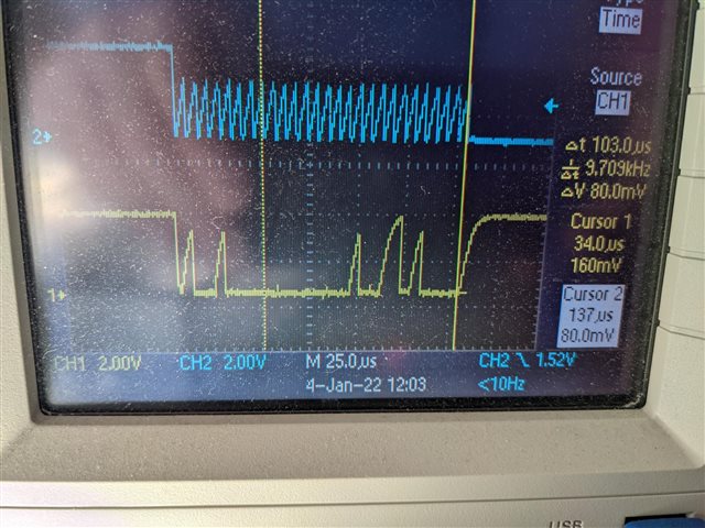
The setup is rather Heath Robinson affair using a controlcard and a TMP1075 from the dev kit:
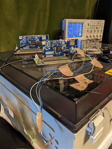
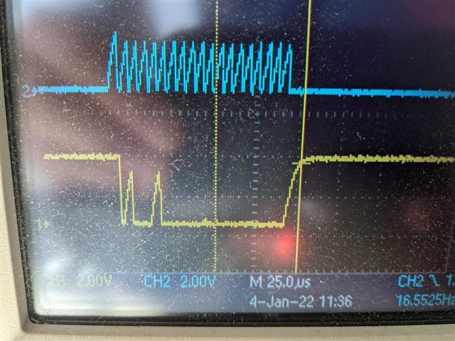
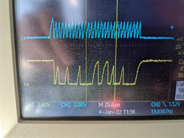
So I'm not expecting perfect signals, but as far as I can tell, the setup is not causing any random behaviour, reducing the I2C bitrate makes no difference to the code behaviour.
I only need to have the I2C to talk to one temperature sensor at this time, so it should be straightforward and ideally I would tirgger a read using asynchronous code and the interrupt would deal with the response as and when the chip is ready, but getting it working like that seems to be causing me some challenges to understand the correct sequencing to make it so. As I said, the code above works reliably, but only after a fashion. It has the following issues:
1) it is relying on the processor delays to manage the I2C timing and whilst I have tried messing about with the driverlib functions to inspect the status of the I2C busy or stop to try and "control" when the I2C start/stop and master send/receive mode changes occur, I have had no success to date, so any suggestions as to how these might be used effectively or if I'm on the right track would be welcome. Or is using external timers to sequence the messages and master mode changes etc the only way?
2) you can see that the while loop in the program seems to cycle twice as many times per interrupt as I would expect and have no idea why this might be. Any ideas? The data on the scope clearly has both bytes being sent in bur for some reason the FIFO is not picking up both bytes each time. Again any suggestions would be welcome.
regards
steve