This thread has been locked.

If you have a related question, please click the "Ask a related question" button in the top right corner. The newly created question will be automatically linked to this question.

TMS320F28027F: I2C scan not blocking

Part Number: TMS320F28027F

Hi everyone, 

I am controlling an external DAC by I2C from the TMS320F28027F. I am able to communicate to it, buy since I will connect several DAC chips to the I2C bus, I want to implement an I2C scan function, which detects if the DAC associated to some address is present or not. 

Just writing the address byte and a second byte (command for the DAC) the external DAC, if present, sets the ACK in the bus and the MASTER (MCU) can set the STOP condition and BB bit is set again to 0. However when the DAC is not present is not setting the ACK to the bus and the master remains alwasy with BB=1 and never sets the STOP condition, so the BUS is not free. 

This is how I init the I2C:

void i2ca_init(void)
{
    I2caRegs.I2CSAR =0x0C;     //0x00001100 DAC address by default

    I2caRegs.I2CMDR.bit.IRS=0;  //Take I2C to reset prior to set the clock
  
    I2caRegs.I2CPSC.all = 6;    // Prescaler - Fmod need 7-12 Mhz on module clk  --> I2C Fmod=(SYSCLKOUT) /(I2CPSC+1)=60/(9+1)=6MHz
    I2caRegs.I2CCLKL = 38;      // Master CLOCK period Tmas=1/Fmod*(I2CCLKL+5+I2CCLKH+5)-->Fmat=100kHz
    I2caRegs.I2CCLKH = 38;       // NOTE: must be non zero
    I2caRegs.I2CIER.all = 0x0;      // Disable interrupts

    I2caRegs.I2CMDR.all = 0x0020;    // Take I2C out of reset
                                     // Stop I2C when suspended
}

Inmediately after the initialitation I execute the next function for scanning, where address is the address to scan in the bus, and the funtion should return 1 if the device is present or 0 if not present:

char I2C_scan_AD5675(char address)
{
static long i=0;
static char device_present=0;

    //Select DAC address
     I2caRegs.I2CSAR =address;     //0x00001100 DAC address for channels 0-7

   // Send start as master transmitter
    //I2caRegs.I2CMDR.all = 0x6E20;
    I2caRegs.I2CMDR.bit.FREE = 1;  //When 1 the I2C module can run even after a breakpoint
    I2caRegs.I2CMDR.bit.MST = 1;    //as master
    I2caRegs.I2CMDR.bit.TRX = 1;    //Transmit
    I2caRegs.I2CMDR.bit.IRS = 1; //to Reset I2C bus.

    I2caRegs.I2CCNT = 1; //I2C_NUMBYTES ;     //on confi

    I2caRegs.I2CMDR.bit.STT = 1;  // Only when MAster, when 1 the Master generates a START condition As soon as you start the Start Bit the BB == 1 becomes busy again.
    I2caRegs.I2CMDR.bit.STP = 1; // Only when Master, when 1 generates a stop condition after I2CCNt=0 will free the BUS thus turning the BB == 0.

    I2caRegs.I2CDXR=0x00; //DAC command

    for (i = 0; i < 10000; i++) {}  //delay loop
    if (I2caRegs.I2CSTR.bit.BB == 1)
      {
        device_present=0;
      }
    else
    {
        device_present=1;
    }
  return device_present;
}

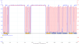
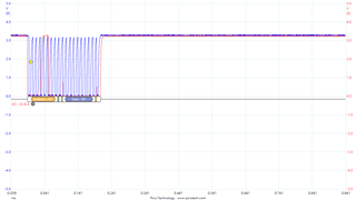
This is the I2C bus snapshot when the DAC is present:
And when the DAC is not present:
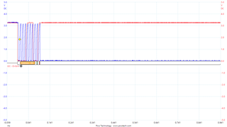
The main problem is that after scan a DAC not present (not present I2C address), the I2C peripheral remains block even if I run the initatilation routine again. 

Any ideas?

Thanks in advance. 

Best regards 

  • Hi, 

    You can check if the NACK bit is set after sending the STOP condition. If it is not set, it will indicate that the slave address is available and if it is set , it will indicate that the slave addresss is not available. 

    Best Regards

    Siddharth

  • Hi Siddharth, 

    Thanks for your kind reply. I have tried next code following your suggestion, and it is working for the first address (it detects or not if the I2C address is present), but after running the function, it does not run it for the next address. Maybe is because after setting the stop condition the bit MST is set to LOW? Is like the I2C is blocked. Should I reset the I2C after each calling?


    char I2C_scan_AD5675_A(char address)
    {
    static char device_present=0;
    
        //Select DAC address
         I2caRegs.I2CSAR =address;     //0x00001100 DAC address for channels 0-7
    
       // Send start as master transmitter
        //I2caRegs.I2CMDR.all = 0x6E20;
        I2caRegs.I2CMDR.bit.FREE = 1;  //When 1 the I2C module can run even after a breakpoint
        I2caRegs.I2CMDR.bit.MST = 1;    //as master
        I2caRegs.I2CMDR.bit.TRX = 1;    //Transmit
        I2caRegs.I2CMDR.bit.RM = 1; //repeat mode
        I2caRegs.I2CMDR.bit.IRS = 1; //to Reset I2C bus.
    
        I2caRegs.I2CCNT = 1; //I2C_NUMBYTES ;     //on confi
    
        I2caRegs.I2CMDR.bit.STT = 1;  // Only when MAster, when 1 the Master generates a START condition As soon as you start the Start Bit the BB == 1 becomes busy again.
        I2caRegs.I2CDXR=0x00;
        while (I2caRegs.I2CSTR.bit.ARDY == 0){}
        I2caRegs.I2CMDR.bit.STP = 1; // Only when Master, when 1 generates a stop condition after I2CCNt=0 will free the BUS thus turning the BB == 0.
    
        if (I2caRegs.I2CSTR.bit.NACK == 1)
          {
            device_present=2;
          }
        else
        {
            device_present=1;
        }  
      return device_present;
    }

    I have tried also another way which is not blocking:

    char I2C_scan_AD5675(char address)
    {
    long i=0;
    static char device_present=0;
      
        //Select DAC address
         I2caRegs.I2CSAR =address;     //0x00001100 DAC address for channels 0-7
    
       // Send start as master transmitter
        //I2caRegs.I2CMDR.all = 0x6E20;
        I2caRegs.I2CMDR.bit.FREE = 1;  //When 1 the I2C module can run even after a breakpoint
        I2caRegs.I2CMDR.bit.MST = 1;    //as master
        I2caRegs.I2CMDR.bit.TRX = 1;    //Transmit
        //I2caRegs.I2CMDR.bit.RM = 1; //repeat mode
        I2caRegs.I2CMDR.bit.IRS = 1; //to Reset I2C bus.
    
        I2caRegs.I2CCNT = 1; //I2C_NUMBYTES ;     //on confi
    
        I2caRegs.I2CMDR.bit.STT = 1;  // Only when MAster, when 1 the Master generates a START condition As soon as you start the Start Bit the BB == 1 becomes busy again.
        I2caRegs.I2CMDR.bit.STP = 1; // Only when Master, when 1 generates a stop condition after I2CCNt=0 will free the BUS thus turning the BB == 0.
    
    
        I2caRegs.I2CDXR=0x00;
    
        for (i = 0; i < 10000; i++){} //delay loop
               if (I2caRegs.I2CSTR.bit.BB == 0)
                 {
                   device_present=1;
                 }
               else
               {
                   device_present=2;
               }
      return device_present;
    }

    With this way I can scanned all the addresses. The problem with it, is that if the last I2C scanned address was not present, it will not execute the I2C writing command for the first I2C present device. Following the function I use for writing a command+data to the I2C device. 

    void setDAC_data(char channel, Uint16 data)
    {
    static char DAC_channel=0;  //individual channel (0-7) in the selected DAC
        //Select DAC address
        if (channel <8)
        {
            I2caRegs.I2CSAR =0x0C;     //0x00001100 DAC address for channels 0-7
            DAC_channel=channel;
        }
        else if (channel<16)
        {
            I2caRegs.I2CSAR =0x0D;     //0x00001101 DAC address for channels 8-15
            DAC_channel=channel-8;
        }
        else if (channel<24)
        {
            I2caRegs.I2CSAR =0x0E;     //0x00001110 DAC address for channels 16-23
            DAC_channel=channel-16;
        }
        else
        {
            I2caRegs.I2CSAR =0x0F;     //0x00001111 DAC address for channels 24-31
            DAC_channel=channel-24;
        }
    
       // Send start as master transmitter
        //I2caRegs.I2CMDR.all = 0x6E20;
        I2caRegs.I2CMDR.bit.FREE = 1;  //When 1 the I2C module can run even after a breakpoint
        I2caRegs.I2CMDR.bit.MST = 1;    //as master
        I2caRegs.I2CMDR.bit.TRX = 1;    //Transmit
        I2caRegs.I2CMDR.bit.IRS = 1; //to Reset I2C bus.
    
        I2caRegs.I2CCNT = 3; //I2C_NUMBYTES ;     //on confi
    
        I2caRegs.I2CMDR.bit.STT = 1;  // Only when MAster, when 1 the Master generates a START condition As soon as you start the Start Bit the BB == 1 becomes busy again.
        I2caRegs.I2CMDR.bit.STP = 1; // Only when Master, when 1 generates a stop condition after I2CCNt=0 will free the BUS thus turning the BB == 0.
    
        while(!I2caRegs.I2CSTR.bit.XRDY){} // Make sure data is ready to be written
        I2caRegs.I2CDXR=0x30|DAC_channel;  //DAC command + Channel
        while(!I2caRegs.I2CSTR.bit.XRDY){} // Make sure data is ready to be written
        I2caRegs.I2CDXR=(char)(data>>8);//0x7F;  //MSB data
        while(!I2caRegs.I2CSTR.bit.XRDY){} // Make sure data is ready to be written
        I2caRegs.I2CDXR=(char)(data&0x00FF);//0xFF;  //LSB data
    
        DAC_data[channel]=data;
    }

    In the main function it looks like this:

    init_I2C (); //set configuration for I2C format and speed 
    
    //SCAN if the 4 possible DACs are present
    test=I2C_scan_AD5675(0x0F);
    if (test==1)DAC_channels=DAC_channels|0xFF000000; //Channels 24-31 present
    test=I2C_scan_AD5675(0x0E);
    if (test==1)DAC_channels=DAC_channels|0x00FF0000; //Channels 16-23 present
    test=I2C_scan_AD5675(0x0D);
    if (test==1)DAC_channels=DAC_channels|0x0000FF00; //Channels 8-15 present
    test=I2C_scan_AD5675(0x0C);
    if (test==1)DAC_channels=DAC_channels|0x000000FF; //Channels 0-7 present
    
    //Set initial data for the I2C devices present
    
    char k=0;
    if ((DAC_channels & 0x000000FF)!=0)
    {
    for (k = 0; k < 8; k++) setDAC_data(k,0); 
    }
    if ((DAC_channels & 0x0000FF00) !=0)
    {
    for (k = 8; k < 16; k++) setDAC_data(k,0); 
    }
    if ((DAC_channels & 0x00FF0000)!=0)
    {
    for (k = 16; k < 23; k++) setDAC_data(k,0); 
    }
    if ((DAC_channels & 0xFF000000) !=0)
    {
    for (k = 24; k < 31; k++) setDAC_data(k,0); 
    }

    In the example if the last address scanned (0x0C) is not present, the function setDAC_data () will be not executed even if it is applied to a present address. 

    Best regards 

  • Hi,

    For the first , can you clear the NACK bit before each address scan. 

    Also, what is the value that you see for the variable DAC_channels if the last address (0xC) is not present.?

    Best Regards

    Siddharth

  • Hi Siddharth, 

    Thanks for yor reply. 

    For the first, it is still not working even clearing NACK before each address scan. Maybe it has to do with the use of the RM mode, that It needs to be used to manually set the STOP condition. I think that if the RM is not selected the STOP condition will be not generated because I2CCNt is not 0 when the address scanned is not present. I can see also that after setting manually the STOP condition the MST bit is set automatically to Low (changing the I2C from Master transmitter to Slave transmitter). Maybe this is the reason for blocking.

    In the function I am using, I set RM=0, so is a pure MASTER transmitter, that should generate automatically the stop condition when I2CCNT=0. Of course when the address is not present  I2CCNT=1 forever so no STOP condition is generated, this is because I check BB bit after a while to determine is the address was present or not. When the address is not present, the STOP condition is not generated so SCL line is held LOW, but this situation is not blocking for the following I2C scans, but strangely it is for the function setDAC_data(k,0), where the MCU acts as Master transmitter writting 3 bytes to the I2C device. 

    About your question on DAC_channels variable, it is working as expected, when the address is present after the I2C scan (test=1) it sets some bits to 1 on the variable. if the address scanned is not present after the scan (test=2) , the variable remains with its previous value. I use  DAC_channels in the next step to write only in those I2C devices (DAC channels) detected. 

    Best regards 

    Green

  • Green, 

    MST is automatically changed from 1 to 0 when the I2C master generates a STOP condition, so this is expected.

    Also, if the repeat mode is selected, the value in I2CCNT is a don't care. 

    What is the value of the I2C status register when you invoke the setDAC_data function  where the MCU acts as Master transmitter writting 3 bytes to the I2C device. ?  What do you mean by blocking - is it not generating the STOP condition?

    Best Regards

    Siddharth

  • Hi Siddharth, 

    Yes, it is not blocking the I2C, the stop condition is always set. The next oscilloscope shot describes better what is happening:

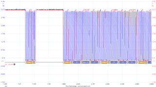
    We see in the picture, the last 2 addresses scanned (0x0F and 0xOE), these 2 devices are not present, so there is no ACK from the slave, and NACK=1. The scanning function is working well as you suggested. However there is a problem if (like in the picture) the last I2C scanned devices is not present. when the funciton setDAC_data is invoked to write 3 bytes (0x30, 0x7F,0x0FF)  in a present device (i.e. 0x0C is present), the first byte which is written is 0x00, the byte that tried to write the last I2C scan, instead of 0x30. 

    It looks like  I2CDXR register is still having it the byte that I2C scan was not able to write to the not present I2C device. Is there any way to empty by software this register? I can see still I2CCNT=1 after scan an I2C devices not present, but I though it was not important when RM=1. 

    The values of I2CSTR=0x0422 and I2CMDR=0x4220 between the last I2C scan and just before the setDAC_data 

    Best regards and thanks in advance. 

  • Hi, 

    You can write the data to  register I2CDXR before generating the START condition. 

    I think the moment you tell the master to generate the START condition, the data in the I2CDXR register is sent out on the bus. 

    So , you can update the code to write the first data byte and then generate the START condition in the setDAC_data function. 

    I2caRegs.I2CMDR.bit.STT = 1;

    Best Regards

    Siddharth

  • Hi Siddharth

    Writing the register I2CDXR with the first byte before the STT condition, is not helping very much. It looks like the count of bytes is done properly:

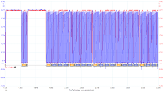
    Each writting should write the command 0x3N + data MSB 0x07 +data LSB 0xFF , in the screen shot you can see the third byte is always missed and the command for the next writting is placed instead. this puzzle me.

    Am I setting the I2caRegs.I2CCNT = 3 in the wrong position? 

    void setDAC_LED(char channel, Uint16 data)
    {
    static char DAC_channel=0;  //individual channel (0-7) in the selected DAC
    
        //Select DAC address
        if (channel <8)
        {
            I2caRegs.I2CSAR =0x0C;     //0x00001100 DAC address for channels 0-7
            DAC_channel=channel;
        }
        else if (channel<16)
        {
            I2caRegs.I2CSAR =0x0D;     //0x00001101 DAC address for channels 8-15
            DAC_channel=channel-8;
        }
        else if (channel<24)
        {
            I2caRegs.I2CSAR =0x0E;     //0x00001110 DAC address for channels 16-23
            DAC_channel=channel-16;
        }
        else
        {
            I2caRegs.I2CSAR =0x0F;     //0x00001111 DAC address for channels 24-31
            DAC_channel=channel-24;
        }
    
       // Send start as master transmitter
        //I2caRegs.I2CMDR.all = 0x6E20;
        I2caRegs.I2CMDR.bit.FREE = 1;  //When 1 the I2C module can run even after a breakpoint
        I2caRegs.I2CMDR.bit.MST = 1;    //as master
        I2caRegs.I2CMDR.bit.TRX = 1;    //Transmit
        I2caRegs.I2CMDR.bit.RM = 0;     //repeat mode off It needs to be set because the RM=1 is used in I2C scan and it can be enabled
        I2caRegs.I2CMDR.bit.IRS = 1; //to Reset I2C bus.
    
    
        //update the I2CDXR before the start condition
        I2caRegs.I2CCNT = 3; //I2C_NUMBYTES ;     //on confi
        I2caRegs.I2CDXR=0x30|DAC_channel;  //DAC command + Channel
    
    
        I2caRegs.I2CMDR.bit.STT = 1;  // Only when MAster, when 1 the Master generates a START condition As soon as you start the Start Bit the BB == 1 becomes busy again.
        I2caRegs.I2CMDR.bit.STP = 1; // Only when Master, when 1 generates a stop condition after I2CCNt=0 will free the BUS thus turning the BB == 0.
    
    
        //write the last 2 bytes
        while(!I2caRegs.I2CSTR.bit.XRDY){} // Make sure data is ready to be written
        I2caRegs.I2CDXR=(char)(data>>8);//0x7F;  //MSB data
        while(!I2caRegs.I2CSTR.bit.XRDY){} // Make sure data is ready to be written
        I2caRegs.I2CDXR=(char)(data&0x00FF);//0xFF;  //LSB data
    
        DAC_data[channel]=data;
    }

  • Hi again, 

    I found a solution where the 3 bytes are written properly, just writing the last byte twice in I2CDXR, but I do not understand why is working now and not before. 

    Here the right oscillospe shot:

    Here the code for the function:

    void setDAC_LED(char channel, Uint16 data)
    {
    static char DAC_channel=0;  //individual channel (0-7) in the selected DAC
        //Select DAC address
        if (channel <8)
        {
            I2caRegs.I2CSAR =0x0C;     //0x00001100 DAC address for channels 0-7
            DAC_channel=channel;
        }
        else if (channel<16)
        {
            I2caRegs.I2CSAR =0x0D;     //0x00001101 DAC address for channels 8-15
            DAC_channel=channel-8;
        }
        else if (channel<24)
        {
            I2caRegs.I2CSAR =0x0E;     //0x00001110 DAC address for channels 16-23
            DAC_channel=channel-16;
        }
        else
        {
            I2caRegs.I2CSAR =0x0F;     //0x00001111 DAC address for channels 24-31
            DAC_channel=channel-24;
        }


       // Send start as master transmitter
        I2caRegs.I2CMDR.bit.FREE = 1;  //When 1 the I2C module can run even after a breakpoint
        I2caRegs.I2CMDR.bit.MST = 1;    //as master
        I2caRegs.I2CMDR.bit.TRX = 1;    //Transmit
        I2caRegs.I2CMDR.bit.RM = 0;     //repeat mode off It needs to be set because the RM=1 is used in I2C scan and it can be enabled
        I2caRegs.I2CMDR.bit.IRS = 1; //to Reset I2C bus.
    
        //update the I2CDXR before the start condition
        I2caRegs.I2CDXR=0x30|DAC_channel;  //DAC command + Channel
    
        I2caRegs.I2CMDR.bit.STT = 1;  // Only when MAster, when 1 the Master generates a START condition As soon as you start the Start Bit the BB == 1 becomes busy again.
        I2caRegs.I2CMDR.bit.STP = 1; // Only when Master, when 1 generates a stop condition after I2CCNt=0 will free the BUS thus turning the BB == 0.
    
        I2caRegs.I2CCNT = 3; //I2C_NUMBYTES ;     //on confi
       
        while(!I2caRegs.I2CSTR.bit.XRDY){} // Make sure data is ready to be written
        I2caRegs.I2CDXR=(char)(data>>8);//0x7F;  //MSB data
        while(!I2caRegs.I2CSTR.bit.XRDY){} // Make sure data is ready to be written
        I2caRegs.I2CDXR=(char)(data&0x00FF);//0xFF;  //LSB data
        while(!I2caRegs.I2CSTR.bit.XRDY){} // Make sure data is ready to be written
        I2caRegs.I2CDXR=(char)(data&0x00FF);//0xFF;  //LSB data
        DAC_data[channel]=data;
    
    }

  • Hi, 

    Can you check for the ARDY bit in your code?  As per the TRM , ARDY indicates that the I2C module registers are ready to be accessed because the previously programmed address, data, and command values have been used. 

    Also, can you ensure that you are not using the I2C FIFO?

    Best Regards

    Siddharth