This thread has been locked.

If you have a related question, please click the "Ask a related question" button in the top right corner. The newly created question will be automatically linked to this question.

RST regulation method TI example

Hi all,

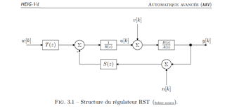
I am trying to implement the RST method regulation for my DC/DC converter.

The RST needs the two/three previous values, do you have any example that stores more than one previous value (z-1, z-2, z-3 ...)

Does TI use RST regulation for any product?

Thank you in advance,

S.Tarik

  • Hi Tarik,

    Could you describe more about RST regulation? What's the full words of 'RST'?

  • R, S, and T are polynomes with z1-, z-2 ... z-n.

    I don't have a very good knowledge of the theoretical background but it looks like this:

  •  

    RST is Reference Signal Tracking (RST).  It is a form of digital regulation loop control which monitors the current and prior two state variables along with the expected power stage transfer function to predict what the next state will be, and adjust the duty cycle to modify that state to match the desired state.


    Your question has been directed to TI's Analog Power Production (APP) Buck Switching Regulator (BSR) Medium Voltage (upto 24V) team.  Our power converter products use analog control loops, even when those analog loops include digitally programmable variables.

    I will see if I can contact someone from TI's Digital Power group, which implement digital control loops.

    Peter James Miller 

  • In the Digital Power group, On our UCD3138x family, we use a PID filter implemented like this:

    TThe stage outputs are added like this:

    We have a limited range error ADC which is paired with a DAC.  The DAC is set to the desired output voltage, which could be considered a reference.  We can change that relatively quickly, and the filter is implemented in hardware.  So if it meets your needs, you could use that.  

    Otherwise, I suggest using a standard DSP and implementing your system in firmware.