This thread has been locked.

If you have a related question, please click the "Ask a related question" button in the top right corner. The newly created question will be automatically linked to this question.

TMS320F280025: fail to program by SCI when connected to ISO7621

Part Number: TMS320F280025
Other Parts Discussed in Thread: ISO7621, ISO6721,

Hi Expert, 

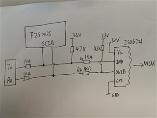
My customer are using F280025, the SCI port is used to communicate with another MCU by connecting to ISO7621 for isolation, but they also want to program the F28002x with the same SCI port by C2prog,

below are schematic they used. with below connection, there will fail to program F28002x by C2prog when ISO6721 is not working, the high level voltage on Tx, Rx will have a little drop, but still is over 3volt. which should be high level for GPIO. 

If they remove the Resistor R4 that connected to ISO7621, then everything is ok. 

customer feedback that the waveform for the first data frame is exactly the same between good case and bad case, only difference is the high voltage level have a little drop to 3volt when at bad case.

questions are:

1. will 3volt for high level voltage impact the SCI communication and cause the issue? 

2. any suggestion for the improving the circuit if they want to share SCI pins for programming device and communicating to other MCU with isolation? 

  • Add the waveform for two case.

    1. TX, RX waveform for good case, green is TX , Yellow is RX for C2000

    2. Bad case, it seem the waveform of RX is the same as good case, but there is no data on TX.

  • Hi,

    Thanks for your questions! To answer them concisely (with details after):
    1. The 3V high level can cause the issue.

    Reason: Looking at the datasheet, during the case where IOH = –100 μA, the minimum VOH is actually VOH = VDDIO – 0.2. If VDDIO is 3.3V, then this would require the VOH to be at least 3.1V (meaning 3V is insufficient).

    2. For circuit improvement, I would recommend tuning the resistor values to provide a higher (3.3V if possible) value at the SCIA-RX/TX pins. Also, I am a bit confused in the diagram of what the "TX and RX" item is on the left of the circuit, since the SCIA is also tied to these pins. Particularly, why there is two different paths to TX/RX, and 10 Ohm resistors on each path.

    I hope this helps with your question!

    Regards,

    Vince

  • Vince,

    Thanks for your suggestion, 

    customer have do the test that remove 10ohm, and also try use the same paths to TX and RX which use the same pullup resistor, but did not help.

  • Hi,

    I believe R3 and R4 are also very high for termination resistors, so I would recommend trying lower values (unless the ISO* part requested 1k specifically).

    Also, could you explain what the device is on the far left of the image?

    Regards,

    Vince

  • Hi,Vince

    Limited by TMS320F280025 CPU resources, this circuit must support SCI communication and serial port programming at the same time (only one is running at the same time).

    ISO6721 defaults to output low level, so R3, R4 must be higher values, otherwise it cannot be output 3.3V high level during serial port programming .

    the device is on the far left of the image is the serial port programmer.

    At present, this problem has not been solved. I measured it with an oscilloscope. The normal programming level can reach 3.3V. If it cannot be programmed normally, the level can reach about 3.15V.

    Now the 10ohm on the left has been changed to 0ohm. R3, R4 have been changed to 3Kohm

    Hope to get your help

  • Hi,

    Thank you for the clarification.

    Can you try making R3 and R4 to 0-ohm? You should be able to keep the pull-up resistors, but all other resistors in that diagram don't seem necessary from my view (they are simply creating an incorrect resistor divider and don't seem to have any need for that).

    Regards,

    Vince

  • Hi Vince,

    customer have try R3 and R4 to 0-ohm, but it did not work.

  • Hi,

    To verify, have you changed all 0 ohms as shown in the diagram below?

    If so, then either the serial port programmer or the other ISO6721 is not outputting a correct 3.3V.

    If that is the case, then unfortunately the only real way to solve this issue is to provide a voltage level shifter for the device(s) that are not communicating at 3.3V.

    Level shifting using resistor dividers as you mentioned will result in a non-ideal voltage at at least one node (since the other two nodes will be benefiting from the voltage division, the 3rd node will no longer be correct).

    Regards,

    Vince