This thread has been locked.

If you have a related question, please click the "Ask a related question" button in the top right corner. The newly created question will be automatically linked to this question.

LAUNCHXL-F28069M: eQep2 Issues

Part Number: LAUNCHXL-F28069M
Other Parts Discussed in Thread: C2000WARE, SYSBIOS

//-----------------------------------------
//  ======== InitEQep2 ========
//-----------------------------------------
void InitEQep2(void)
{

    InitEQep2Gpio();

    EQep2Regs.QUPRD=800000;             // Unit Timer for 100Hz at 80 MHz SYSCLKOUT

    EQep2Regs.QDECCTL.bit.QSRC=00;      // QEP quadrature count mode

    EQep2Regs.QEPCTL.bit.FREE_SOFT=2;

    EQep2Regs.QEPCTL.bit.PCRM=01;       // PCRM=01 mode - Position counter reset on the maximum position (QPOSMAX)
    EQep2Regs.QPOSMAX=4000;             // maximum position (QPOSMAX) is set to 4000 steps

    EQep2Regs.QEPCTL.bit.UTE=1;         // Unit Timeout Enable
    EQep2Regs.QEPCTL.bit.QCLM=1;        // Latch on unit time out

    EQep2Regs.QEPCTL.bit.QPEN=1;        // QEP enable

    EQep2Regs.QCAPCTL.bit.UPPS=5;       // 1/32 for unit position
    EQep2Regs.QCAPCTL.bit.CCPS=6;       // 1/64 for CAP clock
    EQep2Regs.QCAPCTL.bit.CEN=1;        // QEP Capture Enable

}

//-----------------------------------------
//  ======== EncoderMeasurementHWI ========
//-----------------------------------------
Void EncoderMeasurementHWI()
{
    unsigned long Measurement[2] = {0,0};

    DirectionQep++;
//    DirectionQep = EQep2Regs.QEPSTS.bit.QDF;
    CounterQep = (unsigned int)EQep2Regs.QPOSCNT;

    Measurement[0] = DirectionQep;
    Measurement[1] = CounterQep;

    Mailbox_post(EncoderMeasurement, &Measurement, BIOS_NO_WAIT);

    PieCtrlRegs.PIEACK.all = PIEACK_GROUP3;
    EPwm1Regs.ETCLR.bit.INT=1;
}

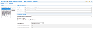
I am generating the quadrature signals with ePWM1 using GPIO0 and GPIO1 and connecting them to GPIO24 and GPIO25 of the eQep2. I verified that ePWM1 is working but I am unable to get eQep2 to register the quadrature signals in software. I am using a RTOS system and configured the eQep2 interrupts as follows.

  • Hi Andrew,

    I am unable to get eQep2 to register the quadrature signals in software.

    Can you further explain what the issue you mean by the above? Are the eQEP signals initialized properly? Are you not seeing the QPOSCNT register go up?

    You could try running the SW example within C2000WARE below as a starting point. You can make changes to the GPIO# config as needed.

    C:\ti\c2000\C2000Ware_4_00_00_00\device_support\f2806x\examples\c28\eqep_freqcal

    Best,

    Kevin

  • The examples works but in my code the HWI (EncoderMeasurementHWI) doesn't get called for this Qep function.

  • Hi Andrew,

    I'm not very familiar with SysBIOS usage unfortunately. If it's related to that specifically then I'll need to ask someone else on our team to comment.

    Comparing the interrupt initialization and registration code of the working example and your project might point to something. I did notice that your Void EncoderMeasurementHWI() function is missing the '__interrupt' that's typically prepended onto an ISR function definition.

    Best,

    Kevin

  • No need for the __interrupt on SYS/BIOS Hwi functions, so no problem there.

    Your Hwi set up seems find to me. How have you configured the QEINT register? I don't see it in your code snippet above. Can you take a look at the registers in CCS--do you see interrupt flags getting set in the QEP registers? What about the PIE registers?

    Whitney

  • //-----------------------------------------
    //  ======== InitEQep2 ========
    //-----------------------------------------
    void InitEQep2(void)
    {
    
        InitEQep2Gpio();
    
        EQep2Regs.QUPRD=800000;             // Unit Timer for 100Hz at 80 MHz SYSCLKOUT
    
        EQep2Regs.QDECCTL.bit.QSRC=00;      // QEP quadrature count mode
    
        EQep2Regs.QEPCTL.bit.FREE_SOFT=2;
    
        EQep2Regs.QEPCTL.bit.PCRM=01;       // PCRM=01 mode - Position counter reset on the maximum position (QPOSMAX)
        EQep2Regs.QPOSMAX=4000;             // maximum position (QPOSMAX) is set to 4000 steps
    
        EQep2Regs.QEPCTL.bit.UTE=1;         // Unit Timeout Enable
        EQep2Regs.QEPCTL.bit.QCLM=1;        // Latch on unit time out
    
        EQep2Regs.QEPCTL.bit.QPEN=1;        // QEP enable
    
        EQep2Regs.QCAPCTL.bit.UPPS=5;       // 1/32 for unit position
        EQep2Regs.QCAPCTL.bit.CCPS=6;       // 1/64 for CAP clock
        EQep2Regs.QCAPCTL.bit.CEN=1;        // QEP Capture Enable
    
    }

    This is how I am configuring the Qep registers

  • Hi Andrew,

    Is the 'EncoderMeasurementHWI()' interrupt intended to be triggered by an ePWM (like the example code) or the eQEP interrupt events? If the latter then, Whitney is right that you need to enable the eQEP interrupts using the QEINT register, which is currently missing in your config.

    Details on the interrupt event generation is below:

    You'll also need change the lines below to clear the eQEP 2 interrupt event:

        PieCtrlRegs.PIEACK.all = PIEACK_GROUP3;
        EPwm1Regs.ETCLR.bit.INT=1;

    Best,

    Kevin

  • I added code to config the int registers and int function.

    void InitEQep2(void)
    {
    
        InitEQep2Gpio();
    
        EQep2Regs.QUPRD=800000;             // Unit Timer for 100Hz at 80 MHz SYSCLKOUT
    
        EQep2Regs.QDECCTL.bit.QSRC=00;      // QEP quadrature count mode
    
        EQep2Regs.QEPCTL.bit.FREE_SOFT=2;
    
        EQep2Regs.QEPCTL.bit.PCRM=01;       // PCRM=01 mode - Position counter reset on the maximum position (QPOSMAX)
        EQep2Regs.QPOSMAX=4000;             // maximum position (QPOSMAX) is set to 4000 steps
    
        EQep2Regs.QEPCTL.bit.UTE=1;         // Unit Timeout Enable
        EQep2Regs.QEPCTL.bit.QCLM=1;        // Latch on unit time out
    
        EQep2Regs.QEPCTL.bit.QPEN=1;        // QEP enable
    
        EQep2Regs.QCAPCTL.bit.UPPS=5;       // 1/32 for unit position
        EQep2Regs.QCAPCTL.bit.CCPS=6;       // 1/64 for CAP clock
        EQep2Regs.QCAPCTL.bit.CEN=1;        // QEP Capture Enable
    
        EQep2Regs.QEINT.bit.IEL=0;          // Index event latch disabled
        EQep2Regs.QEINT.bit.PCM=1;          // eQEP compare match interrupt enabled
        EQep2Regs.QEINT.bit.PCR=0;          // Position-compare ready interrupt disabled
        EQep2Regs.QEINT.bit.PCO=0;          // Position counter overflow interrupt flag disabled
        EQep2Regs.QEINT.bit.PCU=0;          // Position counter underflow interrupt flag disabled
        EQep2Regs.QEINT.bit.QDC=1;          // Quadrature direction change interrupt enabled
    
    
    }
    
    Void EncoderMeasurementHWI()
    {
        unsigned long Measurement[2] = {0,0};
    
    //    DirectionQep++;
        DirectionQep = EQep2Regs.QEPSTS.bit.QDF;
        CounterQep = (unsigned int)EQep2Regs.QPOSCNT;
    
        Measurement[0] = DirectionQep;
        Measurement[1] = CounterQep;
    
        Mailbox_post(EncoderMeasurement, &Measurement, BIOS_NO_WAIT);
    
        PieCtrlRegs.PIEACK.all = PIEACK_GROUP4;
        EQep2Regs.QFLG.bit.INT=1;
    }

    My registers are updating but the EncoderMeasurementHWI is still not getting called.

  • Okay, it looks like the QDC interrupt is enabled and the relevant QFLG bit is set, so you should be getting an interrupt. Can you look at the interrupt registers? Look at PIEIER5 and PIEIFR5 in the PieCtrlRegs and IER, IFR, and ST1.INTM in the Core Registers just to confirm we have all the right enables in place. SYS/BIOS should be taking care of enabling them, but maybe something is interfering...

    Whitney

  • These are what get set in my PIE vector. Is this correct?

  • The PIEIER5 register has the correct bit set to enable the QEP2 interrupt. The PIEIFR5 flag isn't set though. If you put a put a breakpoint in your ISR and set the PIEIFR5 flag manually in the Registers view does it trigger the Hwi?

    Note on your Hwi function--the correct PIEACK group is 5. You probably don't need this line though since you've selected the "automatically acknowledge" option in your Hwi configuration.

    Whitney

  • Whitney,

    Maybe I don't understand what will trigger the interrupt based on my current ISR config of QEP2. Below is what I have so far so can you further explain what would trigger each one of these functions if they were enabled? I am looking to trigger the interrupt after every period of the input signal.

        EQep2Regs.QEINT.bit.IEL=0;          // Index event latch disabled
        EQep2Regs.QEINT.bit.PCM=1;          // eQEP compare match interrupt enabled
        EQep2Regs.QEINT.bit.PCR=0;          // Position-compare ready interrupt disabled
        EQep2Regs.QEINT.bit.PCO=0;          // Position counter overflow interrupt flag disabled
        EQep2Regs.QEINT.bit.PCU=0;          // Position counter underflow interrupt flag disabled
        EQep2Regs.QEINT.bit.QDC=1;          // Quadrature direction change interrupt enabled

  • Descriptions of each of these bits are in the device technical reference manual. A lot of the sections in the TRM have for each of the submodules within the QEP have additional descriptions of what sets the corresponding QFLG bit for each of these.

    Did you try my suggestion of manually setting the PIEIFR bit?

    Whitney

  • I tried to set a break point but I have never been able to get that to work when I use a RTOS. However, I reconfigured my QEINT registers as shown below.

        EQep2Regs.QEINT.bit.IEL=0;          // Index event latch disabled
        EQep2Regs.QEINT.bit.PCM=0;          // eQEP compare match interrupt disabled
        EQep2Regs.QEINT.bit.PCR=0;          // Position-compare ready interrupt disabled
        EQep2Regs.QEINT.bit.PCO=1;          // Position counter overflow interrupt flag enabled
        EQep2Regs.QEINT.bit.PCU=1;          // Position counter underflow interrupt flag enabled
        EQep2Regs.QEINT.bit.QDC=1;          // Quadrature direction change interrupt enabled

    Now the PIE5 registers read as follows.

  • You can try some of the tips in this thread to see if it helps you free up any breakpoints.

    Now that PIEIFR is getting set, is your Hwi function executing? If it's still not working, can you check IER, IFR, and ST1.INTM in the Core Registers?

    Whitney

  • No, the HWI is still not executing.

  • It looks like IFR is getting set but the IER bit to enable INT5 in the CPU isn't set.  If you enable it in IER do you start seeing interrupts? Can you look through your code and see if you are accidentally clearing that bit in IER at some point?

    Whitney

  • This is my code for the HWI. How do I enable the IER? What code would clear the IER?

    //-----------------------------------------
    //  ======== EncoderMeasurementHWI ========
    //-----------------------------------------
    Void EncoderMeasurementHWI()
    {
        unsigned long Measurement[3] = {0,0,0};
    
    //    DirectionQep++;
        DirectionQep = EQep2Regs.QEPSTS.bit.QDF;
        CounterQep = (unsigned int)EQep2Regs.QPOSCNT;
        FreqQep = (unsigned int)EQep2Regs.QCPRD;
    
        Measurement[POS] = CounterQep;
        Measurement[DIR] = DirectionQep;
        Measurement[SPD] = FreqQep;
    
        Mailbox_post(EncoderMeasurement, &Measurement, BIOS_NO_WAIT);
    
        PieCtrlRegs.PIEACK.all = PIEACK_GROUP5;
        EQep2Regs.QFLG.bit.INT=1;
    }

  • Your Hwi function looks fine. Do you write to IER directly in your code anywhere? Do you call any interrupt related functions in your code? If you single step through your code and watch the IER register in the watch window, do you see any functions affecting it?

    Whitney

  • This is the only location where I write to IER directly. This was used for another interrupt.

    // Enable interrupts required for this example
       PieCtrlRegs.PIECTRL.bit.ENPIE = 1;   // Enable the PIE block
       PieCtrlRegs.PIEIER6.bit.INTx1=1;     // Enable PIE Group 6, INT 1
       PieCtrlRegs.PIEIER6.bit.INTx2=1;     // Enable PIE Group 6, INT 2
       IER=0x20;                            // Enable CPU INT6
       EINT;                                // Enable Global Interrupts

  • This code may be your issue. You write IER = 0x20, which enables INT6 but disables all other groups. Does it make a difference if you write IER |= 0x20?

    Do you have a Hwi for this other interrupt? Is there a particular reason why you aren't letting SYS/BIOS handle the PIE and CPU configurations for the interrupt?

    Whitney

  • I was using the example for something else so can I just get rid of all of that code? 
    I ran the code and it now works for eQEP but the interrupt only execute once. I am expecting it to trigger after every count

  • Sorry, I missed it earlier--instead of writing to QFLG to clear the interrupt flags within the QEP registers, you should write to QCLR (QFLG is read only). You not only need to write to the INT bit, but also the bit for the event that caused the interrupt (PCO, PCU, QDC, etc...)

    Whitney