Other Parts Discussed in Thread: TMDSHSECDOCK, C2000WARE,
We are using TMDSCND28388D to check the environment.
Currently, we are checking the following environments.
==================================
CCS |11.1.0.00011
ARM Compiler Tool |20.2.5
C2800 Compiler Tool |21.6.0
==================================
- Connect the dock. (TMDSHSECDOCK)
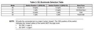
- We want to check it with Flash Boot, so we set the DIP Switch as follows.
s1:a_1 = OFF / s1:a_2 = ON
s2:1 = OFF / s2:2 = ON
- The connectors are connected as follows.
xds200 is connected to JTAG on the dock side.
USB is connected to J17 on the dock side.
- The memory map of CPU1 is not changed.
When I build and load cm4/cpu1/cpu2 from CCS in this environment
When loaded, it works fine, but when reset is pressed when reset is pressed, Flash Boot does not work.
Do I need to deal with the source code or the DEBUG board side?
Please let me know.
The main() of CPU1 is as follows.
===================================
int main(void)
{
DINT;
IER = 0x0000;
IFR = 0x0000;
InitSysCtrl(); // C28 Init & RAM Download & Peripheral Enable Select.
InitGpio();
EALLOW;
CpuSysRegs.PCLKCR10.bit.CAN_B = 1;
EDIS;
GPIO_init(); // GPIO Init Data.
EINT;
/* Wait Core2 boot. */
ars_boot_core2();
/* Wait Cortex-M4 boot. */
ars_boot_cm4();
static U32 t = 0;
while(1) {
if ( t++ > 800000 ) {
GpioDataRegs.GPATOGGLE.bit.GPIO31 = 1;
t = 0;
}
}
return 0;
}
static void ars_boot_core2( void )
{
if ( 1U == DevCfgRegs.RSTSTAT.bit.CPU2RES ) {
Cpu1toCpu2IpcRegs.CPU1TOCPU2IPCBOOTMODE = 0x5A00C803UL; // KEY + Clock Set + BootMode Flash Option0 (sector 0)
Cpu1toCpu2IpcRegs.CPU1TOCPU2IPCSET.bit.IPC0 = 1; // Req to Cpu2.
while ( 1 == Cpu1toCpu2IpcRegs.CPU1TOCPU2IPCFLG.bit.IPC0 ) { // Ack wait.
/* NOP */
}
while( 1 != ( Cpu1toCpu2IpcRegs.CPU2TOCPU1IPCSTS.all & 0xf ) ) { // CPU2 Boot ROM has started running.
/* NOP */
}
}
return;
}
static void ars_boot_cm4( void )
{
// if( 1U == DevCfgRegs.RSTSTAT.bit. )
// {
Cpu1toCmIpcRegs.CPU1TOCMIPCBOOTMODE = 0x5A007D03UL; // KEY + Clock Set + BootMode Flash Option0 (sector 0)
Cpu1toCmIpcRegs.CPU1TOCMIPCSET.bit.IPC0 = 1; // Req to CM4.
while ( 1 == ( Cpu1toCmIpcRegs.CPU1TOCMIPCFLG.bit.IPC0 ) ) { // Ack wait.
/* NOP */
}
while( 1 != ( Cpu1toCmIpcRegs.CMTOCPU1IPCSTS.all & 0xf ) ) { // CM4 Boot ROM has started running.
/* NOP */
}
return;
}