This thread has been locked.

If you have a related question, please click the "Ask a related question" button in the top right corner. The newly created question will be automatically linked to this question.

TMS320F28055: Programming Issue

Part Number: TMS320F28055
Other Parts Discussed in Thread: C2000WARE,

I am in deep stuck  with a  programming issue.  Can  anyone help me?

Chip: TMS320F28055PNT

Programmer/Debugger:  XDS200/XDS110  using 10 pin connector. 

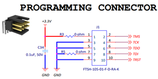
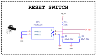
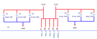
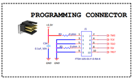
 Programming connection of the microcontroller as below:

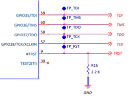
10 pin programming connectors for programmer as below:

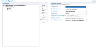
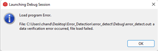
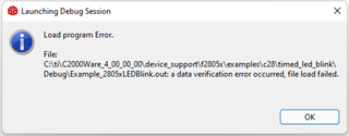
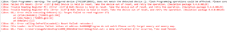
I am getting the below error.

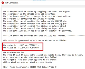
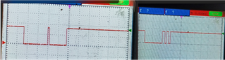
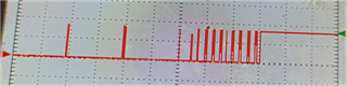
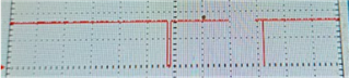
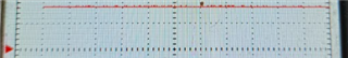
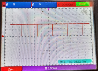
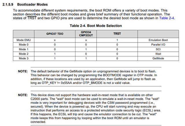
I observe that there is no output from TDO Pin of the controller.

I change Trst pin pull down to 10K instead 2.2K

still getting error.

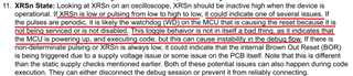
Is there anything more, I am missing?

  • Hello,

    Can you please re-attach the "Programming Connector" image? It appears to be too small to read.

    Here is a helpful link in the meantime: https://software-dl.ti.com/ccs/esd/documents/ccs_debugging_jtag_connectivity_issues.html#invalid-data-read-back Could you also check for the items that it lists?

    Best Regards,

    Marlyn

  • Hi Sudip,

    Everything looks okay in the schematics you have shared. Can you please attach the full report you get after running the 'Test Connection'? Please also ensure that everything is properly soldered and there are no loose connections.

    Best Regards,

    Marlyn

  • Hi Marlyn, 

    1> Every connection is properly soldered and no loose connection present.

    2> the error message as below:-

    [Start: Texas Instruments XDS2xx USB Debug Probe_0]

    Execute the command:

    %ccs_base%/common/uscif/dbgjtag -f %boarddatafile% -rv -o -S integrity

    [Result]


    -----[Print the board config pathname(s)]------------------------------------

    C:\Users\chand\AppData\Local\TEXASI~1\CCS\
    ccs1040\0\0\BrdDat\testBoard.dat

    -----[Print the reset-command software log-file]-----------------------------

    This utility has selected a 560/2xx-class product.
    This utility will load the program 'xds2xxu.out'.
    The library build date was 'Jun 25 2021'.
    The library build time was '16:23:59'.
    The library package version is '9.4.0.00129'.
    The library component version is '35.35.0.0'.
    The controller does not use a programmable FPGA.
    The controller has a version number of '13' (0x0000000d).
    The controller has an insertion length of '0' (0x00000000).
    This utility will attempt to reset the controller.
    This utility has successfully reset the controller.

    -----[Print the reset-command hardware log-file]-----------------------------

    This emulator does not create a reset log-file.

    -----[An error has occurred and this utility has aborted]--------------------

    This error is generated by TI's USCIF driver or utilities.

    The value is '-233' (0xffffff17).
    The title is 'SC_ERR_PATH_BROKEN'.

    The explanation is:
    The JTAG IR and DR scan-paths cannot circulate bits, they may be broken.
    An attempt to scan the JTAG scan-path has failed.
    The target's JTAG scan-path appears to be broken
    with a stuck-at-ones or stuck-at-zero fault.

    [End: Texas Instruments XDS2xx USB Debug Probe_0]

    --------------------------------------------------------------------------------------------------------------

    providing some more info :-

    3> VCC connection PIN as below:-

    4> Controller GND connection as below:-

    5> Analog Part:

    6> TDI PIN:

    7>TCK PIN:

    8> TMS PIN:

    9> TDO PIN:

    finally, No output found  at TDO Pin.

    -sudip

  • Hi Marlyn,

    FYI, The programming Settings as below:-

    -sudip

  • hi Hi Marlyn, FYI, I observed:-

    According to datasheet 2.2k to 10K can make pull up at reset point, controller pin No.8. But i observed that even 470E not able to give 3.2V voltage. i think it is erratic. till now i am not able to solve the problem. waiting for your reply.

  • Hi Sudip,

    The content you provided showed 'XDS2XX', this is different from XDS110, what debug probe are you using the XDS110 or the XDS200? 

    Best Regards,

    Marlyn

  • Hi Sudip,

    Thank you for confirming. Can you please go through this debug guide (https://www.ti.com/lit/spracf0 ) and let me know what step in specific fails for you? This is a resource we provide to narrow down the issue. 

    Best Regards,

    Marlyn

  • hi Marlyn, 

    if no programmer is connected XRSn pin state like as:

    I didn't find the cause.  help me please. 

    -sudip

  • Hi Sudip,

    Do you have the watchdog enabled in your program? 

    Best Regards,

    Marlyn

  • Hi, Marlyn,

    no. it is new board. from start, nothing programmed to this chip. 

    -sudip

  • Hi Sudip,

    Okay, could you please let me know the status of the boot mode pins?

    If possible, please put the device in Emulation Boot and then Wait boot mode, reset the connection under each mode.

    Best Regards,

    Marlyn

  • Hi Marlyn,

    Now scan succeeded.  The status msg as below. 

    -------------------------------------------------------------------------------------------------

    [Start: Texas Instruments XDS2xx USB Debug Probe_0]

    Execute the command:

    %ccs_base%/common/uscif/dbgjtag -f %boarddatafile% -rv -o -S integrity

    [Result]


    -----[Print the board config pathname(s)]------------------------------------

    C:\Users\chand\AppData\Local\TEXASI~1\CCS\
    ccs1040\0\0\BrdDat\testBoard.dat

    -----[Print the reset-command software log-file]-----------------------------

    This utility has selected a 560/2xx-class product.
    This utility will load the program 'xds2xxu.out'.
    The library build date was 'Jun 25 2021'.
    The library build time was '16:23:59'.
    The library package version is '9.4.0.00129'.
    The library component version is '35.35.0.0'.
    The controller does not use a programmable FPGA.
    The controller has a version number of '13' (0x0000000d).
    The controller has an insertion length of '0' (0x00000000).
    This utility will attempt to reset the controller.
    This utility has successfully reset the controller.

    -----[Print the reset-command hardware log-file]-----------------------------

    This emulator does not create a reset log-file.

    -----[Perform the Integrity scan-test on the JTAG IR]------------------------

    This test will use blocks of 64 32-bit words.
    This test will be applied just once.

    Do a test using 0xFFFFFFFF.
    Scan tests: 1, skipped: 0, failed: 0
    Do a test using 0x00000000.
    Scan tests: 2, skipped: 0, failed: 0
    Do a test using 0xFE03E0E2.
    Scan tests: 3, skipped: 0, failed: 0
    Do a test using 0x01FC1F1D.
    Scan tests: 4, skipped: 0, failed: 0
    Do a test using 0x5533CCAA.
    Scan tests: 5, skipped: 0, failed: 0
    Do a test using 0xAACC3355.
    Scan tests: 6, skipped: 0, failed: 0
    All of the values were scanned correctly.

    The JTAG IR Integrity scan-test has succeeded.

    -----[Perform the Integrity scan-test on the JTAG DR]------------------------

    This test will use blocks of 64 32-bit words.
    This test will be applied just once.

    Do a test using 0xFFFFFFFF.
    Scan tests: 1, skipped: 0, failed: 0
    Do a test using 0x00000000.
    Scan tests: 2, skipped: 0, failed: 0
    Do a test using 0xFE03E0E2.
    Scan tests: 3, skipped: 0, failed: 0
    Do a test using 0x01FC1F1D.
    Scan tests: 4, skipped: 0, failed: 0
    Do a test using 0x5533CCAA.
    Scan tests: 5, skipped: 0, failed: 0
    Do a test using 0xAACC3355.
    Scan tests: 6, skipped: 0, failed: 0
    All of the values were scanned correctly.

    The JTAG DR Integrity scan-test has succeeded.

    [End: Texas Instruments XDS2xx USB Debug Probe_0]

    -------------------------------------------------------------------------------------------

    after uploading i am getting the below. error. 

    what to do?

    -sudip

  • Hi Marlyn,

    I am also getting the below message.

    regards-

    sudip

  • Hi Sudip,

    Glad the target configuration test connection now works!

    Here is a link that talks about what data verification errors are and possible causes/solutions: https://software-dl.ti.com/ccs/esd/documents/troubleshooting-data_verification_errors.html 

    As a first form of debug, can you please try loading a C2000Ware example? 

    For example: C:\ti\c2000\C2000Ware_version\device_support\f2805x\examples\c28\timed_led_blink

    If this example loads okay on your hardware then we will know there is something about how you've setup your program and we can continue the debug.

    Best Regards,

    Marlyn

  • Hi Marlyn,

    I am getting the below error when start debugging...

    -sudip

  • Hi Sudip,

    Thank you for trying to load the example. Could you please read the password locations to make sure that the device is unlocked?

    Best Regards,

    Marlyn

  • hi Marlyn,

    Thanks for your reply.

    1. can you provide me info to read the password please?. 

    2. I am observing RST pin state is low. due to this not uploading program? because when trying to upload i am getting the below message.

    -best regards-

    sudip

  • hi Marlyn, 

    Thank you for your support.  The board is programming now. One issue. after removing JTAG, power disconnect and reconnect the board is not running.

    can you please say why board is not running itself. 

    -sudip

  • Hi Sudip,

    Glad to hear it is programming now. If you don't mind me asking, what was the issue? It could help others on here with similar issues.

    can you please say why board is not running itself. 

    Are you flashing the program onto the device or were you only programming into RAM?

    Best Regards,

    Marlyn

  • Hi Marlyn, 

    Our issue was in Hardware. We mixed up VDD and VDDIO. like below:

    We segregate and programing ok. but after reset/power off/on program is not running. please help. what to do. now it running  in Emulation mode. what is the settings option to run stand alone mode.

    -sudip

  • Hi Sudip,

    what is the settings option to run stand alone mode.

    In order for the device to boot up and execute content from Flash please put the device in 'GetMode' by configuring the boot mode pins in the way shown in the table below:

    Best Regards,

    Marlyn

  • Hi Marlyn, Thanks for support.  nothing improve. my sequence as below:-

    1> TRST HI, board power up

    2> connect JTAG and program Timed led blinking example with Emulation. LED blinking.

    3> board power off., remove JTAG

    4> TRST=0, GPIO34=TDO = hi by 1.5K pull up at each pin

    5> power up.

    6> No led blinking program running

    - Best regards

    sudip

  • Hi Sudip,

    No led blinking program running

    My apologies, I was under the impression you were already trying to flash your own program. The LED blinky example only has a RAM configuration and therefore isn't actually getting placed in Flash. 

    Can you please try this program: "flash_f28055" located in the below location:

    C:\ti\c2000\C2000Ware_version\device_support\f2805x\examples\c28\flash_f28055

    Best Regards,

    Marlyn

  • Hi Marlyn,

    Thank you so much for your support. 

    Yes, the said example is running after power recycle. my programming issue solved. 

    best regards-

    sudip

  • Hi Sudip,

    Really glad to hear that! Hope you have a great rest of your day!

    Best Regards,

    Marlyn

  • Hi Marlyn,

    I need to implement TIRTOS in TMS320F28055. is there any example available?

    best regards-

    sudip

  • Hi Sudip,

    Please create a new question on the forum so we can route this to right expert. Someone else should be able to help you setup TIRTOS within your project.

    Best Regards,

    Marlyn

  • Okkk.....Marlyn,....Thanks

    -sudip