This thread has been locked.

If you have a related question, please click the "Ask a related question" button in the top right corner. The newly created question will be automatically linked to this question.

LAUNCHXL-F28379D: Generate shift triangle phase in PWM module using Simulink

Part Number: LAUNCHXL-F28379D

Hi Experts,

Good day.

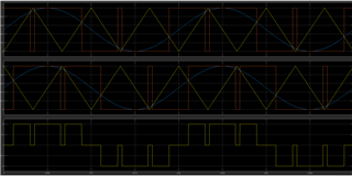
Client is using TMS 28379D Launchpad and would like to generate PWM pulses using it.

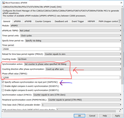
They would like to generate shift triangle phase in PWM module, asking how they could do it?

They are using the using Simulink.

Thank you.

Regards,
Archie A.

  • Archie,

    We're working on getting this assigned to the correct person in the C2000 team, please give us another day.  I'm going to assign based on PWM help, once we get the understanding how to generate the waveform in the ePWM, we can see if the Simulink implementation is similar/straightforward.

    Best,

    Matthew

  • Hi Archie,

    Do you have an image or a sample output waveform of the desired result? This will help me analyze how to achieve this with our devices.

    Best Regards,

    Marlyn

  • Hello Matthew,

    Thanks for redirecting.

    Hi Marlyn,

    Just got update from client for the information required as follows:

    Below attachment is a snap of sinusoidal pulse width modulation. As shown in figure, I would like to compare SINGLE sine wave with TWO PHASE SHIFTED TRIANGLES (180 degree phase shift) for my inverter application.

    How I wanted to implement is mentioned in below steps:

    1. Generated a sine wave as shown in attachment
    2. Selected ePWM block from simulink library
    3. Now generated sine wave is fed to ePWM block.
    4. Inside ePWM block I activated ePWM1A and ePWM1B pins
    5. Everything is working fine and I am getting output as expected for this,

    In the above steps, assuming SINE WAVE (red colour) is compared with TRIANGLE (yellow colour ) to give ePWM1 output. Now how do I compare SINE WAVE (red colour)with TRIANGLE (blue colour ) for get output across ePWM2A and ePWM2B
    pins?

    Thank you.

    Regards,
    Archie A.

  • Hi Archie,

    Thank you for proving more information. Do you know how the Sine wave is currently being compared to the yellow triangle to give epwm1 output?

    Best Regards,

    Marlyn

  • Hello Marlyn,

    Thanks for your response.

    The sine wave from the attachment, as per client, is multiplied with TBPRD value to match the triangle peak value and it fed to ePWM block.

    I am still coordinating with the client if they could share the snapshot of these pulses.

    Regards,
    Archie A.

  • Hi Archie,

    Thank you, what is preventing them from doing the same on EPWM2?

    Best Regards,

    Marlyn

  • Hello Marlyn,

    Following is the response from client:

    "Currently I don't have the processor with me. But, I will tell you what's preventing me from doing ePWM2.

    When I am feeding SINE to ePWM2 block as shown in new attachment. I am getting same output as ePWM1. It means it is comparing SINE wave with TRIANGLE (yellow color from previous attachment). What do I have to change in ePWM2 block so that I can get comparison of SINE with TRIANGLE (Blue colour)

    In the below attachment, the plot in first pane is corresponding to SINE with TRIANGLE (Yellow color in E2 named attachment). Similarly the plot in the second pane is the corresponding to SINE with TRIANGLE (Blue color in E2 named attachment). The plot in the third pane is addition of pulses from plot pane 1 and plot pane 2. And these are the expected waveforms output of ePWM1(first plot pane) and ePWM2 (second plot pane)."

    For your assistance. Thank you.

    Regards,
    Archie A.


  • Hi Archie,

    Thank you for providing further detail. I understand what is needed now. Let me brainstorm a solution for this and get back to you by tomorrow.

    Best Regards,

    Marlyn

  • Hi Archie,

    For EPWM2, the phase needs to be enabled and specified (for the 180 degree phase). The SYNCIN can come from EPWM1.

    Best Regards,

    Marlyn 

  • Hello Marlyn,

    For ePWM2, the client has changed settings as following:

    Also, one more doubt:
    "SYNCIN I have to get from ePWM1? How do I do that? I mean there is no port coming out of ePWM1?"

    Is this correct? Thank you for your guidance.

    Regards,
    Archie A.

  • Hi Archie,

    I would uncheck the "Specify software synchronization via input port" option that is selected within EPWM2, this is for software synchronization which is not needed in this case. 

    "SYNCIN I have to get from ePWM1? How do I do that? I mean there is no port coming out of ePWM1

    Correct, there is no port coming out of EPWM1. The synchronization connection is an internal connection to the device. Please refer to the diagram below. The SYNCO of EPWM1 is fed directly to EPWM2. Therefor, Please set the "Synchronization Output (SYNCO)" of EPWM1 to be when the TBCTR (Time base counter) is equal to zero. This way, every time the time base counter of EPWM1 is equal to 0 it will send the synchronization pulse to EPWM2 and EPWM2 will apply the phase shift value you have defined.

    Best Regards,

    Marlyn

  • Thanks, Marlyn.

    It solved the query.

    Regards,
    Archie A.