Other Parts Discussed in Thread: TMDSCNCD28388D, C2000WARE
Hello,
I am working on a TMS320F28388D CPU located on the TMDSCNCD28388D evaluation board. I wrote an own ‘flash_kernel’ project, which is basically identical with just less functionality compared to the TI ‘flash_kernel’ example.
What I simply want to do is, downloading the blinking LED application of CPU1 to the CPU1 flash and the blinking LED CM application to the CM flash. Afterwards I want to power cycle the board with boot-mode pins set to flash boot and I want to observe that both LEDs are blinking (LED1 by CPU1 and LED2 by CM).
When I download the two applications via JTAG debugger to the corresponding flash, then I see both LEDs blinking after a power cycle the board with boot-mode pins set to flash boot.
From now on I leave the CPU1 flash untouched, that means I have a valid CPU1 blinking LED application on the CPU1 flash!
I download now the CM blinking LED flash application over SCI/CPU1 via my own written ‘flash_kernel’ project to the CM flash memory. I ensured that the data really reach the CM flash at the correct address. But when I now power cycle the board with boot-mode pins set to flash boot, then I see only LED1 blinking by CPU1 but the CM application obviously does not boot from flash.
In order to ensure that my own written ‘flash_kernel’ project isn’t the problem, I verified the behavior with the TI ‘flash_kernel’ project and the ‘serial_flash_programmer.exe’ tool. The problem also exists with the TI example.
Here is what I did:
Step 1
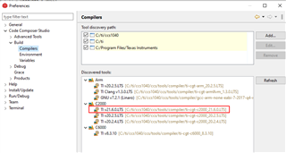
I compiled a CM blinking LED application in build configuration CM_FLASH. As mentioned earlier, I only focus on the CM. The CPU1 blinking LED application already resides on the CPU1 flash and remains untouched.
The ARM hex tool is set up as follows:

I renamed the file generated from the ARM hex utility tool into ‘CM_Flash_Blink.hex.txt’.
Step 2
I erased the flash memory inside the CM and ensured that the flash is empty:

Step 3
I run the ‘serial_flash_programmer.exe’ tool as follows:
serial_flash_programmer.exe -d f2838x -k flash_kernel_c28x_cm_ex1_c28x1.txt -a led_ex1_c28x_cm_blinky_cpu1.txt -o flash_kernel_c28x_cm_ex1_cm.txt -r CM_Flash_Blink.hex.txt -b 9600 -p COM5 -v
Afterwards I select directly option 22 since the application of CPU1 is already on the flash and working.

Step 4
After the CM flash kernel took over control and started running, I selected option 3.


Step 5
I power cycle the evaluation board with boot-mode pins set to flash boot and I see exactly the same behavior as with my own flash kernel project. CPU1 is booting from flash but CM does not boot.
Step 6
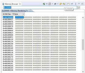
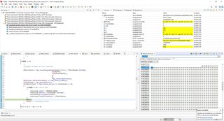
I loaded a RAM application to the CM core, which means that the CM flash remains untouched. Then I looked inside the CM flash application hex file for the content of the flash and verified the data of two sections inside ‘CM_Flash_Blink.hex.txt’ via the memory view (red rectangle = address, green rectangle = data):


It seems that the expected data of the CM application is indeed on the CM flash memory.
Summary
When downloading a CM blinking app flash application to the CM flash memory with either the TI ‘serial_flash_programmer.exe’ tool or with my own PC-tool/flash_kernel project, I see that the data is stored inside the CM flash but the CM does not boot from flash after power cycle the evaluation board with boot-mode pins set to flash boot.
When I download afterwards the CM blinking app flash application to the CM flash memory via the JTAG debugger, then I see the CM booting from flash (the LED 2 blinks) after power cycle the evaluation board with boot-mode pins set to flash boot. The JTAG does obviously something, that the ‘flash_kernel’ misses (e.g. writing entry point to a specific address inside the CM flash?).
Do you have an idea what is wrong?
Thanks,
Inno


