This thread has been locked.

If you have a related question, please click the "Ask a related question" button in the top right corner. The newly created question will be automatically linked to this question.

TMS320F28377D: pulldown resistor tolerance

Part Number: TMS320F28377D
Other Parts Discussed in Thread: SYSCONFIG

Hi,

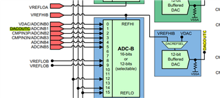
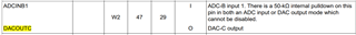
We are driving ADCINB1 from a low-value resistor divider (i.e. no buffer stage). There is a 50-kΩ resistor on this pin. What is the tolerance (%), or min/max of the pull-down resistor? I had a look through the user-manual and datasheet and couldn’t find a reference to the tolerance.

We are about to release our PCB gerbers and so it would be great if you could get back to us quickly, so that we know if a buffer stage is required or not.

BR,

Ross

  • Ross,

    I'll refer you to this app note we created to help derive the optimal setting/circuit for the ADC inputs: https://www.ti.com/lit/spract6 .  The S/H duration is configurable per channel to account for the drive strength on the ADC input pin.  So, you can use a rather large impedance, but mitigate this by sampling the pin longer in order to more accurately charge the internal S/H capacitor.  This will be at the expense of sampling time/speed, but will save the cost of a buffer, etc.  If the resultant sampling/conversion time is too large, then you can look to add a buffer to reduce the needed sampling time.

    There is also an option in our SYSCONFIG tool to input the external R/C on the pin and let it calculate the required S/H value to get a certain accuracy in the conversion vs doing the math described in the app note manually.  You can find this at https://dev.ti.com/  and then SYSCONFIG option.  I've take a screen cap of the tool to help show where this is:

    Let me know if this clears things up, or if you have more questions.

    Best,

    Matthew