This thread has been locked.

If you have a related question, please click the "Ask a related question" button in the top right corner. The newly created question will be automatically linked to this question.

TMS320F28377D: tms320f28377d

Part Number: TMS320F28377D
Other Parts Discussed in Thread: C2000WARE

Hi

Iam using TMS320F28377SPTP_D. 

Am trying to integrate external eeprom 24LC256 using I2C.

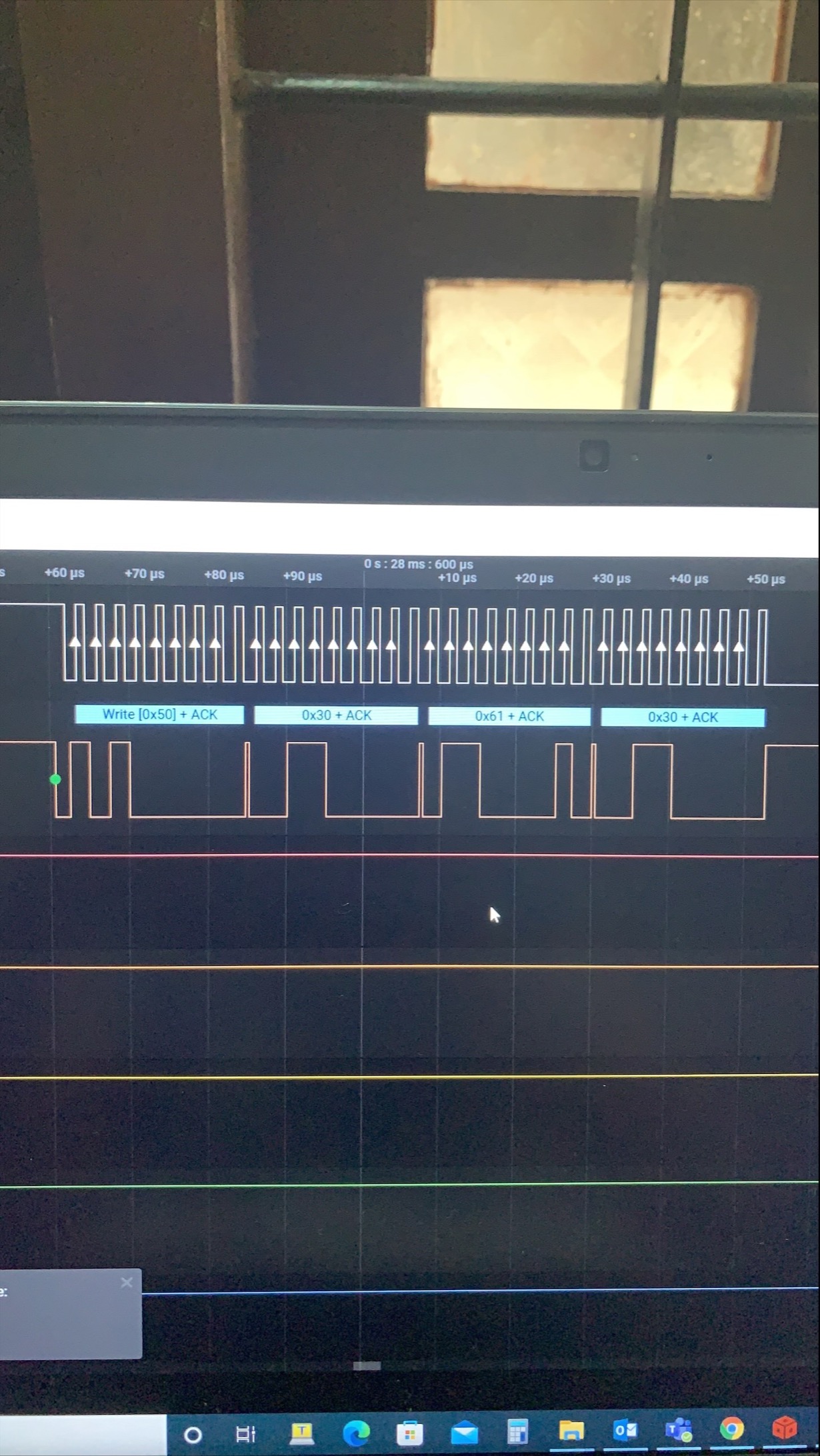
I could start the i2c communication write slave addresses, page addresses and data to eeprom. But read operation is not working.

When I checked with the waveforms, I could see the write operation from start to write operation of data. But after that stop signal is missing in the waveform. 

Below is my init function

void InitI2CA(void)

{

    EALLOW;

    GpioCtrlRegs.GPBDIR.bit.GPIO32 = 0x0;       //SDDA

    GpioCtrlRegs.GPBPUD.bit.GPIO32 = 0x0;       //enable internal pull up

    GpioCtrlRegs.GPBQSEL1.bit.GPIO32 = 0x3;     //Asynchronous operation

    GpioCtrlRegs.GPBGMUX1.bit.GPIO32 = 0x0;

    GpioCtrlRegs.GPBMUX1.bit.GPIO32 = 0x1;


    GpioCtrlRegs.GPBDIR.bit.GPIO33 = 0x0;       //SCLA

    GpioCtrlRegs.GPBPUD.bit.GPIO33 = 0;         //enable internal pull up

    GpioCtrlRegs.GPBQSEL1.bit.GPIO33 = 0x3;     //Asynchronous operation

    GpioCtrlRegs.GPBGMUX1.bit.GPIO33 = 0x0;

    GpioCtrlRegs.GPBMUX1.bit.GPIO33 = 0x1;

    EDIS;


    I2caRegs.I2CSAR.all = 0x50;     // Slave address - EEPROM

    I2caRegs.I2CPSC.all = 19;         // Prescaler, I2C module clock 10MHz

    I2caRegs.I2CCLKL = 10;            // NOTE: must be non zero --SCL 400KHz

    I2caRegs.I2CCLKH = 5;             // NOTE: must be non zero


    I2caRegs.I2CFFTX.all = 0x6000;    // Enable FIFO mode and TXFIFO

    I2caRegs.I2CFFRX.all = 0x2000;    // Enable RXFIFO, clear RXFFINT,

    I2caRegs.I2CMDR.all = 0x0020;     // Take I2C out of reset


}

Below is my write function

void I2C_WriteData_1(char DeviceAddr, char AccessAddr, char data)//char data

{

    if(DeviceAddr == EEPROM_DEVICE)

    {

        I2caRegs.I2CSAR.all = DeviceAddr;           //Slave address

//        I2caRegs.I2CCNT = 1;

        I2caRegs.I2CDXR.all = (AccessAddr >> 8);             // Address high

        I2caRegs.I2CDXR.all = (AccessAddr & 0xFF);          // Address low

        I2cbRegs.I2CMDR.all &= 0x0000;

        I2caRegs.I2CMDR.all |= 0x2620;        //Send start as master transmitter

        I2caRegs.I2CDXR.all = data;


        I2caRegs.I2CMDR.all |= 0x0800;          //Stop i2c


        while (I2caRegs.I2CMDR.bit.STP == 1);

}

}


  • Hi Sharon,

    You may want to reference the C2000WARE I2C EEPROM example 'i2c_ex4_eeprom_polling' or 'i2c_ex6_eeprom_interrupt' in the directory location below. It's a newer example and used the driverLib functions instead of bit-field (which can be more user friendly).

    C:\ti\c2000\C2000Ware_4_00_00_00\driverlib\f2837xd\examples\cpu1\i2c

    In your waveform I only see the write and command portion. For reading, I would expect a repeated start condition with slave address + read bit followed by data being read from the EEPROM. I strongly recommend trying out the other examples and SW framework.

    Best,

    Kevin

  • Hi

    Thankyou for the reply.

    I have checked with all those examples. 

    Even when i call the functions of write and read the waveform looks as below

    I think that my issue is, after write, stop signal is generated in software but not reflecting in the waveform.

  • Hi Sharon,

    From the 24LC256 datasheet below which operation are you trying to execute exactly? From your shared waveform it looks like a 'CURRENT ADDRESS READ'. If so, are you expecting to read back 0xFF?

    https://ww1.microchip.com/downloads/aemDocuments/documents/MPD/ProductDocuments/DataSheets/24AA256-24LC256-24FC256-256-Kbit-I2C-Serial-EEPROM-20001203X.pdf

    In your waveform the 2nd byte has a NACK at the end (F2837x device reading byte from 24LC256) which may be generated instead of a STOP condition if only reading the single byte.

    I think that my issue is, after write, stop signal is generated in software but not reflecting in the waveform.

    What's shown in the latest waveform is a read operation. Do you mean in the original waveform?

    Best,

    Kevin

  • Hi Kevin

    Am trying for a random read from 24LC256. That means initially i will call write function to write the slave addresses, page addresses and data.

    Then i call read fuction which initially contains a write for slave addresses and page addresses. Followed by a read to get data. But whats happening is first write is done and second write is skipped and followed by a read with NAK.

    Is there anything to do for repeated write? Am using RM = 0.

  • Hi Sharon,

    I think what's happening is the 24LC256 is not ready to be read from yet. It may take a few read attempts before the 24LC256 responds with an ACK and the F2837x can read the data from it.

    Have you tried the 'i2c_ex4_eeprom_polling' example in C2000WARE. without making any changes yet? This example should work with no changes and handles the read commands properly. See below from example:

        //Wait for EEPROM write cycle time
        //This delay is not mandatory. User can run their application code instead.
        //It is however important to wait for EEPROM write cycle time before you initiate
        //another read / write transaction
        DEVICE_DELAY_US(EEPROM.WriteCycleTime_in_us);

    Best,

    Kevin