This thread has been locked.

If you have a related question, please click the "Ask a related question" button in the top right corner. The newly created question will be automatically linked to this question.

TMS320F28388D: How to read the MISO lines

Part Number: TMS320F28388D
Other Parts Discussed in Thread: C2000WARE

Hello,

Hope you are doing well.

We are using TMS320F28388D control card and trying to read SPI MISO lines. 

Below is the SPI Configuration.

//mySPI0 initialization

SPI_enableFIFO(mySPI0_BASE);
SPI_setConfig(mySPI0_BASE, DEVICE_LSPCLK_FREQ, SPI_PROT_POL1PHA0,
SPI_MODE_MASTER, 1000000, 8);

SPI_disableLoopback(mySPI0_BASE);
SPI_enableTalk(mySPI0_BASE);
SPI_disableInterrupt(mySPI0_BASE, SPI_INT_TXFF);
SPI_setEmulationMode(mySPI0_BASE, SPI_EMULATION_FREE_RUN);

SPI_enableModule(mySPI0_BASE);

Below is the API we are using to read SPI MISO.

  for(i=0;i<5;i++)
{
SPI_writeDataNonBlocking(mySPI0_BASE, address[i]);
read_data[i] = SPI_readDataNonBlocking(mySPI0_BASE);
}

But when we crosschecked the data received on the MISO lines of SPI between the Oscilloscope and data obtained via SPI_readDataNonBlocking is not matching.

Is there anything that we are doing wrong with respect to SPI configuration or SPI MISO lines reading.

Thanks

Navya Anna Prince

  • Navya,

    From your SPI code snippet above, you're trying to read 5 SPI words from your slave SPI device. correct?

    If so, I strongly recommend you to use SPI_receiveNBytes function available in spi.h (driverlib function). Below function should help you receive 5 SPI words from slave.

    SPI_receiveNBytes(mySPI0_BASE, &read_data, 5, 0U);

    Regards,

    Manoj

  • Hi,

    As per the suggestion I tried to read the MISO lines using below API.

    SPI_receiveNBytes(mySPI0_BASE, &read_data, 5, 0U);

    But the data stored to read_data register is left shifted by one bit

    Also MOSI line is always zero even though i am sending 0x2100000000 data

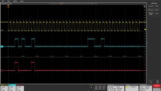
    Below is the OSCILLOSCOPE image captured while reading the register without API.

    Yellow is CLOCK

    Blue is MISO

    Red is MOSI

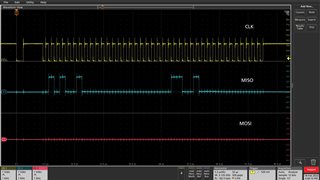
    Below is the OSCILLOSCOPE image captured while reading the register with API.

    On comparing the two images its observed that there is a initial delay in clock. I am curious to know why is this happening. Is this the reason my received data is getting shifting to left by one bit.

    Thanks

     Navya Anna Prince

  • Navya,

    SPI_receiveNBytes does transmit 0x00 to initiate the SPI transaction. So, it is not surprising to see you seeing 0's on MOSI.

    If you want to transmit / receive 'N' byte simulatanously you need to use

    SPI_pollingFIFOTransaction(base, charLength, &TxBuffer, &RxBuffer, numOfWords, txDelay)

    where,

    base = mySPI0_BASE

    charLength = 8U

    TXbuffer should be filled with 0x2100000000

    RXbuffer can be empty

    numOfWords = 5U

    txDelay = 0U  

    "On comparing the two images its observed that there is a initial delay in clock. I am curious to know why is this happening. Is this the reason my received data is getting shifting to left by one bit."

    Are you sure slave and master are working on same clock scheme? I also see lot of ringing noise on the SPI bus. Consider doing impedance matching and clean up your signals

  • Hi,

    As per the suggestion i tried to use  SPI_pollingFIFOTransaction(base, charLength, &TxBuffer, &RxBuffer, numOfWords, txDelay) API to read the MOSI and MISO lines but still getting the same result on the Oscilloscope. Below is the image for the same

    Here in MOSI line i am sending 0x2100000000 but not getting the same on the Oscilloscope. 

    Below is the code for reading the SPI MISO data

    uint32_t SPI_Receive_Multichannel_Motor(uint16_t *address)
    {
    int i=0;

    uint16_t read_data[5] ={0};
    uint32_t receivedData=0;

    SPI_pollingFIFOTransaction(SPIB_BASE, 8U, address, read_data, 5U, 0U);
    SPI_enableFIFO(SPIB_BASE);


    return receivedData;

    }

    And below is the clock scheme for slave and master

  • Navya,

    Here in MOSI line i am sending 0x2100000000 but not getting the same on the Oscilloscope. 

    I'm really concerned with the amount ringing noise of SPI bus. The ringing noise is high enough to cause communication error. That is the reason why I suggested you perform impedance matching.

    Can you just try transmitting a byte and check whether you correctly see 0x21 transmitted in both the methods shown below

    Method1: SPI_transmitByte(SPIB_BASE, 0x21);

    Method2:

    temp = 0x21;

    addr = &temp;

    SPI_pollingFIFOTransaction(SPIB_BASE, 8U, address, read_data, 1U, 0U);

    Can you show me how you are packing the address in 0x2100000000? This is how I would package the data. Is this how you are doing?

    TxData_SPIB[0] = 0x21;

    TxData_SPIB[1] = 0x00;

    TxData_SPIB[2] = 0x00;

    TxData_SPIB[3] = 0x00;

    TxData_SPIB[4] = 0x00;

    address = &TxData_SPIB[0]

    Regards,

    Manoj

  • Also, which SPI slave are you trying to communicate?

  • Hello,

    which SPI slave are you trying to communicate?

    We are trying to connect to TMC5160A motor driver via SPI with TMS320F28388D controller

    Below is the SPI configuration needed for communication

    • SPI Speed : 1Mhz
    • SPI Mode : 3
    • SPI character length : 8
    • Motor driver register length : 40(8 bit address + 32 bit Data)
    • We have to send send 8 bits five times as motor driver register needs 40 bits of data.

    //SPIB GPIO Configuration
    SysCtl_enablePeripheral(SYSCTL_PERIPH_CLK_SPIB);
    GPIO_setPinConfig(GPIO_24_SPIB_SIMO);
    GPIO_setPinConfig(GPIO_25_SPIB_SOMI);
    GPIO_setPinConfig(GPIO_26_SPIB_CLK);
    GPIO_setPinConfig(GPIO_27_SPIB_STEN);

    //mySPIB initialization
    SPI_disableModule(SPIB_BASE);
    SPI_enableFIFO(SPIB_BASE);
    SPI_setConfig(SPIB_BASE, DEVICE_LSPCLK_FREQ, SPI_PROT_POL1PHA0,
    SPI_MODE_MASTER, 1000000, 8);
    SPI_disableLoopback(SPIB_BASE);
    SPI_enableTalk(SPIB_BASE);
    SPI_disableInterrupt(SPIB_BASE, SPI_INT_TXFF);
    SPI_setEmulationMode(SPIB_BASE, SPI_EMULATION_FREE_RUN);
    SPI_enableModule(SPIB_BASE);

    Method1: SPI_transmitByte(SPIB_BASE, 0x21);

    While trying method 1, code is not going to next line of execution . I am guessing since I have enable FIFO in my SPI Configuration its not going to next line.

    Method2:

    temp = 0x21;

    addr = &temp;

    SPI_pollingFIFOTransaction(SPIB_BASE, 8U, address, read_data, 1U, 0U);

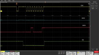
    Above is the Oscilloscope image for sending 8 bits with SPI_pollingFIFOTransaction(SPIB_BASE, 8U, address, read_data, 1U, 0U);

    Can you show me how you are packing the address in 0x2100000000? 

    uint32_t Get_Motor_Register_X(uint16_t Address)
    {
    uint16_t *SPI_Data=0;
    uint32_t received_data=0;
    SPI_Data[0]=Address;
    SPI_Data[1]=0;
    SPI_Data[2]=0;
    SPI_Data[3]=0;
    SPI_Data[4]=0;
    received_data= SPI_Receive_X_Motor(SPI_Data); //Here i am calling the API for SPI Transmit and SPI Response
    ;

    return received_data;

    }

    The ringing noise is high enough to cause communication error. That is the reason why I suggested you perform impedance matching.

    i am sorry i didn't understand by impedance matching. Could you elaborate a little on this?

    Thanks

    Navya

  • Method1: SPI_transmitByte(SPIB_BASE, 0x21);

    While trying method 1, code is not going to next line of execution . I am guessing since I have enable FIFO in my SPI Configuration its not going to next line.

    I see you have configured SPI chip select pin as SPI pin and not GPIO pin. You need to configure SPI chip select pin as GPIO output pin and do the following. When you mentioned the code was stuck, it should have stuck in SPI_writeDataBlockingNonFIFO function waiting for the transmission to complete.

    Also, don't enable the SPI FIFO when you use SPI_transmitByte function

    You can check spi_ex6_eeprom (C2000Ware example), this shows how the how these driver lib APIs are used.

    1) Pull GPIO (used for chipselect) LOW

    2) SPI_transmitByte(SPIB_BASE, 0x21)

    The ringing noise is high enough to cause communication error. That is the reason why I suggested you perform impedance matching.

    i am sorry i didn't understand by impedance matching. Could you elaborate a little on this?

    This is a basic electrical engineering topic and taken care during the pcb design. There is lot of material online when search for impedance matching. Ringing noise I see on your SPI bus (spikes on SPI signals) can lead to communication issues.

    From TI, we have this appnote which covers this topic with respect to SDFM peripheral but the concepts are universal and can be applied to SPI

    Achieving Better Signal Integrity With Isolated Delta-Sigma Modulators in Motor Drives (https://www.ti.com/lit/tida033)

    Regards,

    Manoj