This thread has been locked.

If you have a related question, please click the "Ask a related question" button in the top right corner. The newly created question will be automatically linked to this question.

TMS320F28035: when as slave device, one interrupt sequence error happen

Part Number: TMS320F28035

{
    // Initialize I2C-A:
    EALLOW;
    SysCtrlRegs.PCLKCR0.bit.I2CAENCLK = 1;     // I2C

    GpioCtrlRegs.GPBPUD.bit.GPIO32 = 0;    // Enable pull-up for GPIO32 (SDAA)
    GpioCtrlRegs.GPBPUD.bit.GPIO33 = 0;    // Enable pull-up for GPIO33 (SCLA)

    GpioCtrlRegs.GPBQSEL1.bit.GPIO32 = 3;  // Asynch input GPIO32 (SDAA)
    GpioCtrlRegs.GPBQSEL1.bit.GPIO33 = 3;  // Asynch input GPIO33 (SCLA)

    GpioCtrlRegs.GPBMUX1.bit.GPIO32 = 1;   // Configure GPIO32 for SDAA operation
    GpioCtrlRegs.GPBMUX1.bit.GPIO33 = 1;   // Configure GPIO33 for SCLA operation
    EDIS;

    I2caRegs.I2CMDR.bit.IRS = 0;            //I2C Reset bit.
    I2caRegs.I2CMDR.bit.MST = 0;            //@NOTE: 0=slave mode; 1=master mode.
    I2caRegs.I2CMDR.bit.XA  = 0;            //@NOTE: 0=7bit address; 1=10bit address.
    I2caRegs.I2CMDR.bit.BC  = 0x00;         //@NOTE: 0=8 bits per data byte
    I2caRegs.I2CMDR.bit.NACKMOD = 0;        //I2C Reset bit.
    I2caRegs.I2CEMDR.bit.BCM  = 0x00;

    I2C_SetPMbusAddress(SLAVE_ADDRESS_INIT);

    I2caRegs.I2CIER.bit.AAS = 1;            //Addressed as slave interrupt enable 1h (R/W) = Interrupt request enabled
    I2caRegs.I2CIER.bit.SCD = 1;            //Stop condition detected interrupt enable 1h (R/W) = Interrupt request enabled
                                            //this for non-PEC check
    I2caRegs.I2CIER.bit.RRDY = 1;           //receive ready
    I2caRegs.I2CIER.bit.XRDY = 1;           //transmit ready

    I2caRegs.I2CSAR = 0x0000;       // The next address.
    I2caRegs.I2CPSC.bit.IPSC = 5;   // Prescaler - need 7-12 Mhz on module clk (60/6 = 10MHz)
                                    // module clock frequency = I2C input clock frequency/(IPSC + 1)

    // 10MHz/(45+5 + 45 +5) = 100K
    I2caRegs.I2CCLKL = 45;          // NOTE: must be non zero
    I2caRegs.I2CCLKH = 45;          // NOTE: must be non zero

    I2caRegs.I2CMDR.bit.IRS = 1;            //I2C Reset bit.  Take I2C out of reset

    I2caRegs.I2CFFTX.all = 0x0000;  // Enable FIFO mode and TXFIFO
    I2caRegs.I2CFFRX.all = 0x0000;  // Enable RXFIFO, clear RXFFINT,
}

initial as I2C slave device.

enable 4 type interrupt

    I2caRegs.I2CIER.bit.AAS = 1;            //Addressed as slave interrupt enable 1h (R/W) = Interrupt request enabled
    I2caRegs.I2CIER.bit.SCD = 1;            //Stop condition detected interrupt enable 1h (R/W) = Interrupt request enabled
                                            //this for non-PEC check
    I2caRegs.I2CIER.bit.RRDY = 1;           //receive ready
    I2caRegs.I2CIER.bit.XRDY = 1;           //transmit ready

ISR code

{
    Uint16 u16IntSrcReg;
//    static Uint16 i = 0;
//    static Uint16 j = 0;

    u16IntSrcReg = (Uint16)I2caRegs.I2CISRC.bit.INTCODE;

	switch(u16IntSrcReg)
	{
		case 0x01:
			//Arbitration lost
		break;	
		case 0x02:
			//No-acknowledgment condition detected
		break;	
		case 0x03:
			//Registers ready to be accessed
		break;	
		case 0x04:
		    //while(I2caRegs.I2CFFRX.bit.RXFFST < 4)  {};
		    j= 0;
		    if(I2caRegs.I2CSTR.bit.SDIR == 1)
		    {
		        //
		    }
		    else//slave read data
		    {

                RxData[i] = I2caRegs.I2CDRR;
                command = RxData[0];
                if(i>=6)
                {
                    i=0;
                }
                else
                {
                    i++;
                    if((command_type == 1)&&(command == 0x99))//command length =1
                    {
                        i=0;
                    }
                }
		    }


		break;	
		case 0x05://Transmit data ready

            if(command == 0x99)
            {
                //while(!I2C_xrdy());

                //while(I2caRegs.I2CSTR.bit.XRDY != 1) {};// 1 = Data transferred tp the core TX register after shifting data
                if(j>=7)
                {
                    I2caRegs.I2CDXR = 0xFF;
                }
                else
                {
                    I2caRegs.I2CDXR = Array[j];
                }
                j++;
            }
            else
            {
                I2caRegs.I2CDXR = 0xFF;
            }


		break;	
		case 0x06:
			//Stop condition detected
		break;		
		case 0x07:
			//Addressed as slave
			if(I2caRegs.I2CSTR.bit.SDIR == 1)  //means address read
			{
			    //address read
			    I2C_bIsSlaveAddressRead();
			}
			else
			{
			    //I2caRegs.I2CIER.bit.XRDY = 0;//address write
			    //I2caRegs.I2CMDR.bit.TRX = 0;
			    I2C_bIsSlaveAddressWrite();
			    //i=0;

			}
		break;			
		default:
			//error happen
		break;
	}	


    PieCtrlRegs.PIEACK.all = PIEACK_GROUP8;   //release other interrupt
}

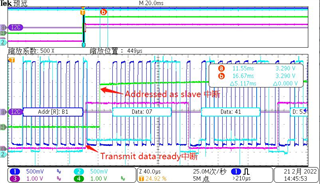
when I add test pin in the code, get below waveform.

channel 3: toggle when XRDY happen    channel4: toggle when AAS happen.

question: why AAS happen before than XRDY? if I need to exchange it, how to config the I2C module?  thanks!

  • Sorry, correct error:

    question: why AAS happen after than XRDY? if I need to exchange it, how to config the I2C module?

  • Hi Zhuo,

    I think it would help debug further if you set the IO to XRDY and AAS state rather than toggling the IO.

    XRDY will get set (HIGH) when I2CDXR is ready to accept more data, i.e. when the previous data has been copied from I2CDXR to the transmit shift register (I2CXSR). I2CDXR could be ready for more data before the slave device ACKs the address. AAS bit will be set after the device ACKs the address (as seen in your waveform).

    Also, AAS interrupt is lower priority than XRDY interrupt which may have an impact on your debug.

    Best,

    Kevin

  • Hi Kevin,

    Thanks for your help!

    in my application, I must add CRC-8 at the end I2C package.

    for example:

    S SlaveAddress w CMD Sr SlaveAddress r DataLo DataHi CRC8 P

    only AAS happen before than XRDY, CRC8 will be calculated right.

    I will do an experiment, only AAS read interrupt happen, then enable XRDY interrupt. will it work?

    another question:

    I can find the spec about “AAS interrupt is lower priority than XRDY interrupt ”, could you kindly point out?

    about your suggestion("set the IO, not toggle IO"), it's a good idea, I accept.

    Thank you very much!

  • Hi Zhuo,

    S SlaveAddress w CMD Sr SlaveAddress r DataLo DataHi CRC8 P

    only AAS happen before than XRDY, CRC8 will be calculated right.

    I will do an experiment, only AAS read interrupt happen, then enable XRDY interrupt. will it work?

    I'd like to clarify your needs. The CRC8 is being calculated for the DataLo and DataHi bytes? And this CRC8 is what the F2803x slave device calculates and sends back to the master device, correct? If so, I think your experiment will work, where you'd re-enable XRDY interrupt in the AAS interrupt case.

    I can find the spec about “AAS interrupt is lower priority than XRDY interrupt ”, could you kindly point out?

    Good observation, it's actually still missing from the F2803x TRM. This info will be added in the next revision. The below is taken from the newer F28002x device TRM for your reference, the I2C modules are essentially the same between F2803x and F28002x.

    Best,

    Kevin

  • Hi Kevin,

    Thank for your help!

    I'd like to clarify your needs. The CRC8 is being calculated for the DataLo and DataHi bytes?

    CRC8 is calculated from "SlaveAddress w" to "DataHi".

    And this CRC8 is what the F2803x slave device calculates and sends back to the master device, correct?

    Yes, slave device will report CRC8 to master side.

    Actually, it does work now. " only AAS read interrupt happen, then enable XRDY interrupt"

    Thanks for your photo, it's clear now.

    Best regards,

    Kaka