Part Number: TMS320F28020
Other Parts Discussed in Thread: TMS320F28021
Hi All,
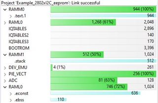
I'm quickly running out of memory on a TMS320F28020 project after adding code for only two of the several peripherals that will be needed. The project is a port from an ATMEGA328PB-MU processor written in C/C++. The Atmega part has 32kBytes Flash, 1kByte EEPROM, and 2kBytes SRAM, and its memory isn't maxed out even with all the modules implemented and working.
Here's the C2000 scenario:
I2C Implementation:
1. Starting with "Example_2802xI2c_eeprom.c" bitfield code downloaded from the "Resource Explorer"
2. on a LaunchPadXL TMS320F2802x
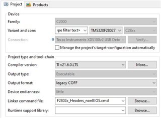
3. in CCS ver. 10.4.0.00006
4. with Compiler ver. TI v21.6.0LTS
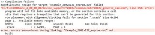
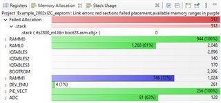
5. I added a switch statement along with a small amount of related code, and it has pretty much maxed out memory.
//###########################################################################
//
// FILE: Example_2802xI2c_eeprom.c
//
// TITLE: f2802x I2C EEPROM Example
//
// ASSUMPTIONS:
//
// This program requires the f2802x header files.
//
// This program requires an external I2C EEPROM connected to
// the I2C bus at address 0x50.
//
// As supplied, this project is configured for "boot to SARAM"
// operation. The 2802x Boot Mode table is shown below.
// For information on configuring the boot mode of an eZdsp,
// please refer to the documentation included with the eZdsp,
//
// $Boot_Table
// While an emulator is connected to your device, the TRSTn pin = 1,
// which sets the device into EMU_BOOT boot mode. In this mode, the
// peripheral boot modes are as follows:
//
// Boot Mode: EMU_KEY EMU_BMODE
// (0xD00) (0xD01)
// ---------------------------------------
// Wait !=0x55AA X
// I/O 0x55AA 0x0000
// SCI 0x55AA 0x0001
// Wait 0x55AA 0x0002
// Get_Mode 0x55AA 0x0003
// SPI 0x55AA 0x0004
// I2C 0x55AA 0x0005
// OTP 0x55AA 0x0006
// Wait 0x55AA 0x0007
// Wait 0x55AA 0x0008
// SARAM 0x55AA 0x000A <-- "Boot to SARAM"
// Flash 0x55AA 0x000B
// Wait 0x55AA Other
//
// Write EMU_KEY to 0xD00 and EMU_BMODE to 0xD01 via the debugger
// according to the Boot Mode Table above. Build/Load project,
// Reset the device, and Run example
//
// $End_Boot_Table
//
// DESCRIPTION:
//
// This program will write 1-14 words to EEPROM and read them back.
// The data written and the EEPROM address written to are contained
// in the message structure, I2cMsgOut1. The data read back will be
// contained in the message structure I2cMsgIn1.
//
// This program will work with the on-board I2C EEPROM supplied on
// the F2802x eZdsp.
//
//
//###########################################################################
// $TI Release: F2802x Support Library v3.05.00.00 $
// $Release Date: 10-19-2021 $
// $Copyright:
// Copyright (C) 2009-2021 Texas Instruments Incorporated - http://www.ti.com/
//
// Redistribution and use in source and binary forms, with or without
// modification, are permitted provided that the following conditions
// are met:
//
// Redistributions of source code must retain the above copyright
// notice, this list of conditions and the following disclaimer.
//
// Redistributions in binary form must reproduce the above copyright
// notice, this list of conditions and the following disclaimer in the
// documentation and/or other materials provided with the
// distribution.
//
// Neither the name of Texas Instruments Incorporated nor the names of
// its contributors may be used to endorse or promote products derived
// from this software without specific prior written permission.
//
// THIS SOFTWARE IS PROVIDED BY THE COPYRIGHT HOLDERS AND CONTRIBUTORS
// "AS IS" AND ANY EXPRESS OR IMPLIED WARRANTIES, INCLUDING, BUT NOT
// LIMITED TO, THE IMPLIED WARRANTIES OF MERCHANTABILITY AND FITNESS FOR
// A PARTICULAR PURPOSE ARE DISCLAIMED. IN NO EVENT SHALL THE COPYRIGHT
// OWNER OR CONTRIBUTORS BE LIABLE FOR ANY DIRECT, INDIRECT, INCIDENTAL,
// SPECIAL, EXEMPLARY, OR CONSEQUENTIAL DAMAGES (INCLUDING, BUT NOT
// LIMITED TO, PROCUREMENT OF SUBSTITUTE GOODS OR SERVICES; LOSS OF USE,
// DATA, OR PROFITS; OR BUSINESS INTERRUPTION) HOWEVER CAUSED AND ON ANY
// THEORY OF LIABILITY, WHETHER IN CONTRACT, STRICT LIABILITY, OR TORT
// (INCLUDING NEGLIGENCE OR OTHERWISE) ARISING IN ANY WAY OUT OF THE USE
// OF THIS SOFTWARE, EVEN IF ADVISED OF THE POSSIBILITY OF SUCH DAMAGE.
// $
//###########################################################################
//
// Included Files
//
#include "DSP28x_Project.h" // Device Headerfile and Examples Include File
//
// Note: I2C Macros used in this example can be found in the
// f2802x_I2C_defines.h file
//
//
// Function Prototypes
//
void I2CA_Init(void);
uint16_t I2CA_WriteData(struct I2CMSG *msg);
__interrupt void i2c_int1a_isr(void);
void pass(void);
void fail(void);
//
// Defines
//
#define I2C_SLAVE_ADDR 0x50
#define I2C_NUMBYTES 2
#define I2C_EEPROM_HIGH_ADDR 0x00
#define I2C_EEPROM_LOW_ADDR 0x30
//
// Globals
//
struct I2CMSG I2cMsgOut1=
{
I2C_MSGSTAT_SEND_WITHSTOP,
I2C_SLAVE_ADDR,
I2C_NUMBYTES,
I2C_EEPROM_HIGH_ADDR,
I2C_EEPROM_LOW_ADDR,
//
// Msg Byte 1
//
0x12,
//
// Msg Byte 2
//
0x34
};
struct I2CMSG I2cMsgIn1=
{
I2C_MSGSTAT_SEND_NOSTOP,
I2C_SLAVE_ADDR,
I2C_NUMBYTES,
I2C_EEPROM_HIGH_ADDR,
I2C_EEPROM_LOW_ADDR
};
uint16_t delayCounter = 0;
volatile unsigned int volumeCommand[40];
volatile int redSwitchCurrent = 0;
volatile int redSwitchPrevious = 0;
volatile int greenSwitchCurrent = 0;
volatile int greenSwitchPrevious = 0;
volatile int transmitStringFlag = 0;
//
// Used in interrupts
//
struct I2CMSG *CurrentMsgPtr;
uint16_t PassCount;
uint16_t FailCount;
volatile uint16_t idleCounter1;
volatile uint16_t idleCounter2;
volatile uint16_t tempByte = 0;
// vv Tim's code vv
//PARSING PORTION
/*****************************************************************************
*
*****************************************************************************/
enum Command
{
NONE, QET, RET, SRC, QRC, QMS, IVI, DVI, SVI, QVI, SRS, QPW, SVO, IVO, DVO, QVO, SLD, SOS
} ;
/*****************************************************************************
*
*****************************************************************************/
struct CommandMessage
{
enum Command cmd;
short value1;
short value2;
};
// ^^ Tim's code ^^
void TransmitString(int numBytes);
struct CommandMessage cm; // This works
//
// Main
//
void main(void)
{
uint16_t Error;
uint16_t i;
//
// WARNING: Always ensure you call memcpy before running any functions from
// RAM InitSysCtrl includes a call to a RAM based function and without a
// call to memcpy first, the processor will go "into the weeds"
#ifdef _FLASH
memcpy(&RamfuncsRunStart, &RamfuncsLoadStart, (size_t)&RamfuncsLoadSize);
#endif
// CurrentMsgPtr = &I2cMsgOut1;
//
// Step 1. Initialize System Control:
// PLL, WatchDog, enable Peripheral Clocks
// This example function is found in the f2802x_SysCtrl.c file.
//
InitSysCtrl();
//
// Step 2. Initialize GPIO:
// This example function is found in the f2802x_Gpio.c file and
// illustrates how to set the GPIO to it's default state.
//
//InitGpio();
//
// Setup only the GP I/O only for I2C functionality
//
InitI2CGpio();
//
// Step 3. Clear all interrupts and initialize PIE vector table:
// Disable CPU interrupts
//
DINT;
//
// Initialize PIE control registers to their default state.
// The default state is all PIE interrupts disabled and flags
// are cleared.
// This function is found in the f2802x_PieCtrl.c file.
//
InitPieCtrl();
//
// Disable CPU interrupts and clear all CPU interrupt flags
//
IER = 0x0000;
IFR = 0x0000;
//
// Initialize the PIE vector table with pointers to the shell Interrupt
// Service Routines (ISR).
// This will populate the entire table, even if the interrupt
// is not used in this example. This is useful for debug purposes.
// The shell ISR routines are found in f2802x_DefaultIsr.c.
// This function is found in f2802x_PieVect.c.
//
InitPieVectTable();
//
// Interrupts that are used in this example are re-mapped to
// ISR functions found within this file.
//
EALLOW; // This is needed to write to EALLOW protected registers
PieVectTable.I2CINT1A = &i2c_int1a_isr;
EDIS; // This is needed to disable write to EALLOW protected registers
//
// Step 4. Initialize all the Device Peripherals
//
I2CA_Init(); // I2C-A only
//
// Step 5. User specific code
//
//
// Clear Counters
//
PassCount = 0;
FailCount = 0;
//
// Clear incoming message buffer
//
for (i = 0; i < (I2C_MAX_BUFFER_SIZE - 2); i++)
{
// I2cMsgIn1.MsgBuffer[i] = 0x0000;
}
//
// Enable interrupts required for this example
//
//
// Enable I2C interrupt 1 in the PIE: Group 8 interrupt 1
//
PieCtrlRegs.PIEIER8.bit.INTx1 = 1;
//
// Init GPIOs (rdv)
//
EALLOW;
GpioCtrlRegs.GPAMUX1.bit.GPIO4 = 0; // 0 configures GPIO4 as GPIO
GpioCtrlRegs.GPADIR.bit.GPIO4 = 0; // 0 makes it an input
GpioCtrlRegs.GPAPUD.bit.GPIO4 = 0; // 0 enables pull-up
GpioCtrlRegs.GPAMUX1.bit.GPIO5 = 0; // 0 configures GPIO5 as GPIO
GpioCtrlRegs.GPADIR.bit.GPIO5 = 0; // 0 makes it an input
GpioCtrlRegs.GPAPUD.bit.GPIO5 = 0; // 0 enables pull-up
GpioCtrlRegs.GPAMUX2.bit.GPIO19 = 0; // 0 configures GPIO19 as GPIO
GpioCtrlRegs.GPADIR.bit.GPIO19 = 1; // 1 makes it an output
GpioCtrlRegs.GPAPUD.bit.GPIO19 = 0; // 0 enables pull-up
EDIS;
// GpioDataRegs.GPASET.bit.GPIO19 = 1;
GpioDataRegs.GPACLEAR.bit.GPIO19 = 1;
//
// Enable CPU INT8 which is connected to PIE group 8
//
IER |= M_INT8;
EINT;
//
// Application loop
//
//
// Temp debug vars
//
volumeCommand[0] = 0xfe;
volumeCommand[1] = 0x51;
volumeCommand[2] = 0xfe;
volumeCommand[3] = 0x45;
volumeCommand[4] = 0x00;
volumeCommand[21] = 0xfe;
volumeCommand[22] = 0x45;
volumeCommand[23] = 0x40;
cm.cmd = 0;
cm.value1 = 0;
cm.value2 = 0;
for(;;)
{
if(delayCounter++ > 1)
{
delayCounter = 0;
redSwitchCurrent = GpioDataRegs.GPADAT.bit.GPIO4; // Get switch states
greenSwitchCurrent = GpioDataRegs.GPADAT.bit.GPIO5;
if(redSwitchCurrent != redSwitchPrevious) // Compare to previous state
{
if(!redSwitchCurrent & redSwitchPrevious){ // If the button change is from a press, not release...
transmitStringFlag = 1;
cm.cmd++;
if(cm.cmd > SOS) // Increment to next command
{
cm.cmd = NONE; // Roll to first command
}
}
redSwitchPrevious = redSwitchCurrent; // Update previous state to current
}
if(greenSwitchCurrent != greenSwitchPrevious) // Compare to previous state
{
if(!greenSwitchCurrent & greenSwitchPrevious){ // If the button change is from a press, not release...
transmitStringFlag = 1;
cm.cmd--;
if(cm.cmd <= NONE) // Increment to next command
{
cm.cmd = SOS; // Roll to first command
}
}
greenSwitchPrevious = greenSwitchCurrent; // Update previous state to current
}
if(transmitStringFlag)
{
switch(cm.cmd)
{
case NONE: // 0
{
short numBytes = 40;
strcpy(volumeCommand+5, " NONE ");
// 1234567890123456
strcpy(volumeCommand+24,"**Bottom line**. ");
// 1234567890123456
volumeCommand[21] = 0xfe;
TransmitString(numBytes);
transmitStringFlag = 0;
}
break;
case QET: // 1
{
short numBytes = 40;
strcpy(volumeCommand+5, " QET ");
// 1234567890123456
strcpy(volumeCommand+24,"**Bottom line**. ");
// 1234567890123456
volumeCommand[21] = 0xfe;
TransmitString(numBytes);
transmitStringFlag = 0;
}
break;
case RET: // 2
{
short numBytes = 40;
strcpy(volumeCommand+5, " RET ");
// 1234567890123456
strcpy(volumeCommand+24,"**Bottom line**. ");
// 1234567890123456
volumeCommand[21] = 0xfe;
TransmitString(numBytes);
transmitStringFlag = 0;
}
break;
case SRC: // 3
{
short numBytes = 40;
strcpy(volumeCommand+5, " SRC ");
// 1234567890123456
strcpy(volumeCommand+24,"**Bottom line**. ");
// 1234567890123456
volumeCommand[21] = 0xfe;
TransmitString(numBytes);
transmitStringFlag = 0;
}
break;
case QRC: // 4
{
short numBytes = 40;
strcpy(volumeCommand+5, " QRC ");
// 1234567890123456
strcpy(volumeCommand+24,"**Bottom line**. ");
// 1234567890123456
volumeCommand[21] = 0xfe;
TransmitString(numBytes);
transmitStringFlag = 0;
}
break;
case QMS: // 5
{
short numBytes = 40;
strcpy(volumeCommand+5, " QMS ");
// 1234567890123456
strcpy(volumeCommand+24,"**Bottom line**. ");
// 1234567890123456
volumeCommand[21] = 0xfe;
TransmitString(numBytes);
transmitStringFlag = 0;
}
break;
case IVI: // 6
{
short numBytes = 40;
strcpy(volumeCommand+5, " IVI ");
// 1234567890123456
strcpy(volumeCommand+24,"**Bottom line**. ");
// 1234567890123456
volumeCommand[21] = 0xfe;
TransmitString(numBytes);
transmitStringFlag = 0;
}
break;
case DVI: // 7
{
short numBytes = 40;
strcpy(volumeCommand+5, " DVI ");
// 1234567890123456
strcpy(volumeCommand+24,"**Bottom line**. ");
// 1234567890123456
volumeCommand[21] = 0xfe;
TransmitString(numBytes);
transmitStringFlag = 0;
}
break;
case SVI: // 8
{
short numBytes = 40;
strcpy(volumeCommand+5, " SVI ");
// 1234567890123456
strcpy(volumeCommand+24,"**Bottom line**. ");
// 1234567890123456
volumeCommand[21] = 0xfe;
TransmitString(numBytes);
transmitStringFlag = 0;
}
break;
case QVI: // 9
{
short numBytes = 40;
strcpy(volumeCommand+5, " QVI ");
// 1234567890123456
strcpy(volumeCommand+24,"**Bottom line**. ");
// 1234567890123456
volumeCommand[21] = 0xfe;
TransmitString(numBytes);
transmitStringFlag = 0;
}
break;
case SRS: // 10
{
short numBytes = 40;
strcpy(volumeCommand+5, " SRS ");
// 1234567890123456
strcpy(volumeCommand+24,"**Bottom line**. ");
// 1234567890123456
volumeCommand[21] = 0xfe;
TransmitString(numBytes);
transmitStringFlag = 0;
}
break;
case QPW: // 11
{
short numBytes = 40;
strcpy(volumeCommand+5, " QPW ");
// 1234567890123456
strcpy(volumeCommand+24,"**Bottom line**. ");
// 1234567890123456
volumeCommand[21] = 0xfe;
TransmitString(numBytes);
transmitStringFlag = 0;
}
break;
case SVO: // 12
{
short numBytes = 40;
strcpy(volumeCommand+5, " SVO ");
// 1234567890123456
strcpy(volumeCommand+24,"**Bottom line**. ");
// 1234567890123456
volumeCommand[21] = 0xfe;
TransmitString(numBytes);
transmitStringFlag = 0;
}
break;
case IVO: // 13
{
short numBytes = 40;
strcpy(volumeCommand+5, " IVO ");
// 1234567890123456
strcpy(volumeCommand+24,"**Bottom line**. ");
// 1234567890123456
volumeCommand[21] = 0xfe;
TransmitString(numBytes);
transmitStringFlag = 0;
}
break;
case DVO: // 14
{
short numBytes = 40;
strcpy(volumeCommand+5, " DVO ");
// 1234567890123456
strcpy(volumeCommand+24,"**Bottom line**. ");
// 1234567890123456
volumeCommand[21] = 0xfe;
TransmitString(numBytes);
transmitStringFlag = 0;
}
break;
case QVO: // 15
{
short numBytes = 40;
strcpy(volumeCommand+5, " QVO ");
// 1234567890123456
strcpy(volumeCommand+24,"**Bottom line**. ");
// 1234567890123456
volumeCommand[21] = 0xfe;
TransmitString(numBytes);
transmitStringFlag = 0;
}
break;
case SLD: // 16
{
short numBytes = 40;
strcpy(volumeCommand+5, " SLD ");
// 1234567890123456
strcpy(volumeCommand+24,"**Bottom line**. ");
// 1234567890123456
volumeCommand[21] = 0xfe;
TransmitString(numBytes);
transmitStringFlag = 0;
}
break;
case SOS: // 17
{
short numBytes = 40;
strcpy(volumeCommand+5, " SOS ");
// 1234567890123456
strcpy(volumeCommand+24,"**Bottom line**. ");
// 1234567890123456
volumeCommand[21] = 0xfe;
TransmitString(numBytes);
transmitStringFlag = 0;
}
break;
default: // Anything else
{
short numBytes = 40;
strcpy(volumeCommand+5, " Command ");
// 1234567890123456
strcpy(volumeCommand+24,"was out of range");
// 1234567890123456
volumeCommand[21] = 0xfe;
TransmitString(numBytes);
transmitStringFlag = 0;
}
break;
}
}
}
}
}
//
// I2CA_Init -
//
void
I2CA_Init(void)
{
// Initialize I2C
I2caRegs.I2CMDR.bit.IRS = 0; // SEE BELOW - Put I2C module in reset while making changes
//
// Own Address Register
// // Bit 15: READ ONLY - Reserved
I2caRegs.I2COAR = 0x26; // Own address = 0x28
// Bits 7-15: Reserved
//
// I2C Interrupt Enable Register
// // Bits 7-15: READ ONLY - Reserved
I2caRegs.I2CIER.bit.AAS = 0; // Bit 6: 1 = Addressed as slave interrupt request enabled
I2caRegs.I2CIER.bit.SCD = 0; // Bit 5: 1 = Stop condition detected interrupt request enabled
I2caRegs.I2CIER.bit.XRDY = 0; // Bit 4: 1 = Transmit data ready interrupt request disabled
I2caRegs.I2CIER.bit.RRDY = 0; // Bit 3: 1 = W1C - Receive data ready interrupt request enabled
I2caRegs.I2CIER.bit.ARDY = 0; // Bit 2: 1 = Master Only - Register access ready interrupt request enabled
I2caRegs.I2CIER.bit.NACK = 0; // Bit 1: 0 = W1C - No-ack interrupt request disabled
I2caRegs.I2CIER.bit.ARBL = 0; // Bit 0: 0 = W1C - Arbitration lost interrupt request disabled
//
// I2C Status Register
// // Bit 15: READ ONLY - Reserved
I2caRegs.I2CSTR.bit.SDIR = 1; // Bit 14: W1C - Slave direction bit 0 = not addressed as slave transmitter
I2caRegs.I2CSTR.bit.NACKSNT = 1; // Bit 13: W1C - NACK sent bit 0 = NACK not sent
I2caRegs.I2CSTR.bit.BB = 0; // Bit 12: Bus Busy bit 0 = bus free
I2caRegs.I2CSTR.bit.RSFULL = 0; // Bit 11: 1 = receive shift register overrun condition detected
I2caRegs.I2CSTR.bit.XSMT = 0; // Bit 10: 0 = transmit shift register underflow detected (empty)
I2caRegs.I2CSTR.bit.AAS = 0; // Bit 9: 1 = I2C module recognized its own slave address
I2caRegs.I2CSTR.bit.AD0 = 0; // Bit 8: 1 = address of all zeros (general call) was detected
// Bits 6-7: READ ONLY - Reserved
I2caRegs.I2CSTR.bit.SCD = 1; // Bit 5: W1C - 1 = stop condition was detected
I2caRegs.I2CSTR.bit.XRDY = 1; // Bit 4: 1 = Ready for more transmit data to go in I2CDXR
I2caRegs.I2CSTR.bit.RRDY = 1; // Bit 3: W1C - Receive data ready int flag 1 = data is in I2CDRR
I2caRegs.I2CSTR.bit.ARDY = 1; // Bit 2: Master Only - Register access ready int flag
I2caRegs.I2CSTR.bit.NACK = 1; // Bit 1: W1C - 1 = NACK received
I2caRegs.I2CSTR.bit.ARBL = 1; // Bit 0: W1C - 1 = arbitration lost
//
// I2C Clock Prescale Register
//
// Setup I2C data rate
I2caRegs.I2CPSC.bit.IPSC = 5; // Prescaler value 60mHz SYSCLK / 6 = 10mHz (5+1=6)
//
// I2C Clock high-time and low-time Registers
//
// 10mHz / 200 = 50kHz for comm's with 2x16 debugging display
I2caRegs.I2CCLKL = 129; // 129 + 5 = 136
I2caRegs.I2CCLKH = 61; // 61 + 5 = 66
//
// Data Count Register
//
I2caRegs.I2CCNT = 1; // Bits 0-15: Set data count (ignored in RM mode)
// Is changed to actual number of bytes to transfer when in
// transmit mode.
//
// Slave Address Register
// // Bits 10-15: READ ONLY - Reserved
I2caRegs.I2CSAR = 0x28; // Bits 0-9: Address to which data will be transmitted (Master only)
//
// I2C Mode Register
// // Bits 14-15: READ ONLY - Reserved
I2caRegs.I2CMDR.bit.NACKMOD = 0; // Bit 15: NACK mode
I2caRegs.I2CMDR.bit.FREE = 0; // Bit 14: For debugging: 0 = I2C halts during interrupts
// I2caRegs.I2CMDR.bit.STT = 0; // Bit 13: Master only - Start bit Can't be written when IRS=0
// Bit 12: Reserved
// I2caRegs.I2CMDR.bit.STP = 0; // Bit 11: Master only - Stop bit Can't be written when IRS=0
I2caRegs.I2CMDR.bit.MST = 1; // Bit 10: Remains 0 for slave mode. 1 = Master mode
I2caRegs.I2CMDR.bit.TRX = 1; // Bit 9: 0 = Receive mode, 1 = Transmit mode
I2caRegs.I2CMDR.bit.XA = 0; // Bit 8: 0 = 7 bit address mode
I2caRegs.I2CMDR.bit.RM = 1; // Bit 7: 1 = repeat mode
I2caRegs.I2CMDR.bit.DLB = 0; // Bit 6: 0 = Digital loopback mode disabled
// I2caRegs.I2CMDR.bit.IRS = 1; // Bit 5: I2C module is re-enabled after making changes
I2caRegs.I2CMDR.bit.STB = 0; // Bit 4: Master only - Start Byte mode
I2caRegs.I2CMDR.bit.FDF = 0; // Bit 3: Keep at 0. Free data format mode
I2caRegs.I2CMDR.bit.BC = 0; // Bits 0-2: Set bit count to 8 bits (0 = 8)
//
// I2C Extended Mode Register
// // Bits 1-15: READ ONLY - Reserved
I2caRegs.I2CEMDR.bit.BCM = 0; // Bit 0: Backwards compatibility mode
//
// Transmit FIFO Register
// // Bits 14-15: READ ONLY - Reserved
// Bit 15: Reserved
I2caRegs.I2CFFTX.bit.I2CFFEN = 0; // Bit 14: 1 = Enable transmit & receive FIFOs
I2caRegs.I2CFFTX.bit.TXFFRST = 0; // Bit 13: 1 = Take transmit FIFO out of reset
// I2caRegs.I2CFFTX.bit.TXFFST = 0; // Bits 8-12: READ ONLY - How many bytes are in the transmit FIFO
// I2caRegs.I2CFFTX.bit.TXFFINT = 0; // Bit 7: READ ONLY - 1 = interrupt occurred
I2caRegs.I2CFFTX.bit.TXFFINTCLR = 1; // Bit 6: W1C - Clears transmit interrupt flag (do again after irs = 1)
I2caRegs.I2CFFTX.bit.TXFFIENA = 0; // Bit 5: 0 = Disable transmit FIFO interrupt
I2caRegs.I2CFFTX.bit.TXFFIL = 0; // Bits 0-4: Set the transmit FIFO interrupt Threshold
//
// Receive FIFO Register
// // Bits 14-15: READ ONLY - Reserved
I2caRegs.I2CFFRX.bit.RXFFRST = 0; // Bit 13: 1 = enable receive FIFO operation
// I2caRegs.I2CFFRX.bit.RXFFST = 0; // BitS 8-12: READ ONLY - Bytes in receive FIFO
// I2caRegs.I2CFFRX.bit.RXFFINT = 0; // Bit 7: READ ONLY - Receive interrupt flag 1 = int
I2caRegs.I2CFFRX.bit.RXFFINTCLR = 1; // Bit 6: Write 1 to clear receive int flag
I2caRegs.I2CFFRX.bit.RXFFIENA = 0; // Bit 5: 1 = receive interrupt is enabled
I2caRegs.I2CFFRX.bit.RXFFIL = 0; // Bits 0-4: Set the receive FIFO interrupt level
// Clean up and exit
I2caRegs.I2CMDR.bit.IRS = 1; // SEE ABOVE - I2C module is re-enabled after making changes
I2caRegs.I2CFFTX.bit.TXFFINTCLR = 1; // SEE ABOVE - Clears transmit interrupt flag
I2caRegs.I2CFFRX.bit.RXFFINTCLR = 1; // SEE ABOVE - Clears receive interrupt flag
return;
}
//
// Transmit String -
//
void
TransmitString(int numBytes)
{
uint16_t i;
uint16_t i2;
// wait for STOP condition
while (I2caRegs.I2CMDR.bit.STP != 0); //bus is not occupied
// generate START condition
I2caRegs.I2CMDR.bit.STT = 1;// resets once the START condition is issued
for(i = 0; i < numBytes; i++){
idleCounter1 = 0;
while(!I2caRegs.I2CSTR.bit.XRDY)
{
if(idleCounter1++ >= 60000) // 30,000 ~ 12.6ms
// When the master read happens before data is ready (after the master sends a write)
// XRDY is never satisfied. This algorithm senses this condition and after a time
// (~12.6ms) reads the I2CDRR to clear the I2C bus condition.
// Extending this delay makes the data transfer more robust, but at the expense of
// extending the GMS trip response (during this delay).
//
//
// This is to help unstick the bus when too many writes are issued
{ // by master w/o reading. It must be long enough to allow master
idleCounter1 = 0; // enough time to download bytes normally.
tempByte = I2caRegs.I2CDRR; // It must be short enough to allow quick end to CPU hogging
// The following resets I2C xmit buffer in case master doesn't pull all data
I2caRegs.I2CMDR.bit.IRS = 0; // Put I2C module in reset while making changes
I2caRegs.I2CCNT = 0; // Set data count to 0 clears xmit buffer
I2caRegs.I2CMDR.bit.IRS = 1; // I2C module is re-enabled after making changes
}
}
// wait for XRDY flag to transmit data
// while (I2caRegs.I2CSTR.bit.XRDY != 1);//wait for the XRDY (transmit mode ready) bit of the status register, which means that the data transmit register is ready to accept new data.
I2caRegs.I2CDXR = volumeCommand[i]; // Loads a value into the data xmit buffer, starting the xmit process
// I2caRegs.I2CMDR.all = 0x6E20;
for(i2=0; i2<2500; i2++)
{
// Do nothing, just wait
}
}
// snd stop condition here
I2caRegs.I2CMDR.bit.STP = 1;
/*
idleCounter2 = 0;
while(I2caRegs.I2CSTR.bit.BB)
{
if(idleCounter2++ >= 1000) // This is to help unstick the bus when xmit buffer empties
{
idleCounter2 = 0;
I2caRegs.I2CDXR = 0xdb;
}
}
*/
I2caRegs.I2CMDR.all = 0x06a0; // Resets the I2C mode register
}
uint16_t I2CA_WriteData(struct I2CMSG *msg)
{
uint16_t i;
uint16_t i2;
// wait for STOP condition
while (I2caRegs.I2CMDR.bit.STP != 0); //bus is not occupied
// generate START condition
I2caRegs.I2CMDR.bit.STT = 1;// resets once the START condition is issued
for(i = 0; i < 40; i++){
idleCounter1 = 0;
while(!I2caRegs.I2CSTR.bit.XRDY)
{
if(idleCounter1++ >= 60000) // 30,000 ~ 12.6ms
// When the master read happens before data is ready (after the master sends a write)
// XRDY is never satisfied. This algorithm senses this condition and after a time
// (~12.6ms) reads the I2CDRR to clear the I2C bus condition.
// Extending this delay makes the data transfer more robust, but at the expense of
// extending the GMS trip response (during this delay).
//
//
// This is to help unstick the bus when too many writes are issued
{ // by master w/o reading. It must be long enough to allow master
idleCounter1 = 0; // enough time to download bytes normally.
tempByte = I2caRegs.I2CDRR; // It must be short enough to allow quick end to CPU hogging
// The following resets I2C xmit buffer in case master doesn't pull all data
I2caRegs.I2CMDR.bit.IRS = 0; // Put I2C module in reset while making changes
I2caRegs.I2CCNT = 0; // Set data count to 0 clears xmit buffer
I2caRegs.I2CMDR.bit.IRS = 1; // I2C module is re-enabled after making changes
}
}
// wait for XRDY flag to transmit data
// while (I2caRegs.I2CSTR.bit.XRDY != 1);//wait for the XRDY (transmit mode ready) bit of the status register, which means that the data transmit register is ready to accept new data.
// generate START condition
// I2caRegs.I2CMDR.bit.STT = 1;// resets once the START condition is issued
I2caRegs.I2CDXR = volumeCommand[i]; // Loads a value into the data xmit buffer, starting the xmit process
// I2caRegs.I2CMDR.all = 0x6E20;
for(i2=0; i2<2500; i2++) {
// Do nothing, just wait
}
}
// snd stop condition here
I2caRegs.I2CMDR.bit.STP = 1;
idleCounter2 = 0;
while(I2caRegs.I2CSTR.bit.BB)
{
if(idleCounter2++ >= 1000) // This is to help unstick the bus when xmit buffer empties
{
idleCounter2 = 0;
I2caRegs.I2CDXR = 0xdb;
}
}
I2caRegs.I2CMDR.all = 0x06a0; // Resets the I2C mode register
return I2C_SUCCESS;
}
//
// i2c_int1a_isr - I2C-A
//
__interrupt void
i2c_int1a_isr(void)
{
uint16_t IntSource, i;
//
// Read interrupt source
//
IntSource = I2caRegs.I2CISRC.all;
//
// Interrupt source = stop condition detected
//
if(IntSource == I2C_SCD_ISRC)
{
//
// If completed message was writing data, reset msg to inactive state
//
if (CurrentMsgPtr->MsgStatus == I2C_MSGSTAT_WRITE_BUSY)
{
CurrentMsgPtr->MsgStatus = I2C_MSGSTAT_INACTIVE;
}
else
{
//
// If a message receives a NACK during the address setup portion
// of the EEPROM read, the code further below included in the
// register access ready interrupt source code will generate a stop
// condition. After the stop condition is received (here), set the
// message status to try again. User may want to limit the number
// of retries before generating an error.
//
if(CurrentMsgPtr->MsgStatus == I2C_MSGSTAT_SEND_NOSTOP_BUSY)
{
CurrentMsgPtr->MsgStatus = I2C_MSGSTAT_SEND_NOSTOP;
}
//
// If completed message was reading EEPROM data, reset msg to
// inactive state and read data from FIFO.
//
else if (CurrentMsgPtr->MsgStatus == I2C_MSGSTAT_READ_BUSY)
{
CurrentMsgPtr->MsgStatus = I2C_MSGSTAT_INACTIVE;
for(i=0; i < I2C_NUMBYTES; i++)
{
CurrentMsgPtr->MsgBuffer[i] = I2caRegs.I2CDRR;
}
//
// Check received data
//
for(i=0; i < I2C_NUMBYTES; i++)
{
if(I2cMsgIn1.MsgBuffer[i] == I2cMsgOut1.MsgBuffer[i])
{
PassCount++;
}
else
{
FailCount++;
}
}
if(PassCount == I2C_NUMBYTES)
{
pass();
}
else
{
fail();
}
}
}
}
//
// Interrupt source = Register Access Ready
// This interrupt is used to determine when the EEPROM address setup
// portion of the read data communication is complete. Since no stop bit is
// commanded, this flag tells us when the message has been sent instead of
// the SCD flag. If a NACK is received, clear the NACK bit and command a
// stop. Otherwise, move on to the read data portion of the communication.
//
else if(IntSource == I2C_ARDY_ISRC)
{
if(I2caRegs.I2CSTR.bit.NACK == 1)
{
I2caRegs.I2CMDR.bit.STP = 1;
I2caRegs.I2CSTR.all = I2C_CLR_NACK_BIT;
}
else if(CurrentMsgPtr->MsgStatus == I2C_MSGSTAT_SEND_NOSTOP_BUSY)
{
CurrentMsgPtr->MsgStatus = I2C_MSGSTAT_RESTART;
}
}
else
{
//
// Generate some error due to invalid interrupt source
//
__asm(" ESTOP0");
}
//
// Enable future I2C (PIE Group 8) interrupts
//
PieCtrlRegs.PIEACK.all = PIEACK_GROUP8;
}
//
// pass -
//
void
pass()
{
__asm(" ESTOP0");
for(;;);
}
//
// fail -
//
void
fail()
{
__asm(" ESTOP0");
for(;;);
}
//
// End of File
//
SCIA Implementation:
1. Running "Example_2802xScia_FFDLB.c" Bitfield code downloaded from the "Resource Explorer"
2. on a LaunchPadXL TMS320F2802x
3. in CCS ver. 10.4.0.00006
4. with Compiler ver. TI v21.6.0LTS
I'm not able to get these two modules to run together, because of insufficient memory. I will still need to add functionality for:
1. ADC
2. GPIO
3. Flash memory IO
4. User interface
Questions:
1. The Atmega part is an 8-bit processor, whereas the 28020 is 32-bit. Was it wrong to assume what fit into 32kbytes of memory on the 8-bit part would fit in 32kbytes on a 32-bit part?
2. Can a significant amount of the example code be eliminated, while maintaining the ability for simple I2C and SCIA communications? With I2C, the 28020 is the master, and the slave doesn't respond with data (ACK only).
3. I can switch to a TMS320F28021 for 64k, but will that be enough?
I would appreciate insight from anyone who can help.
Thanks,
robin