This thread has been locked.
If you have a related question, please click the "Ask a related question" button in the top right corner. The newly created question will be automatically linked to this question.
BACKGROUND: Using LAUNCHXL-F280025C development board, and kept all of the jumper setting unaltered.
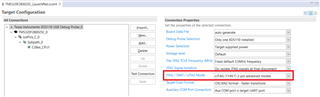
Loaded code and am able to see the change of variables in CCS WATCH WINDOW in run time.
All four jumbers @J101 in all four locations are present, this means XDS_TXD, XDS_RXD, XDS_TMS_SWDIO, XDS_TCK_SWDTCK are shorted to
MCU_RXD, MCU_TXD, MCU_TMS, MCU_TCK. However TDO and TDI from MCU side in NOT connected to onboard XDS110.
Q1: Even if remove J101 jumpers @ MCU_RXD, MCU_TXD signals, I can still see variables changing in watch window ? This means for my activity: TCK and TMS signals are sufficient. Then what these two signals: MCU_RXD, MCU_TXD used for in this board ?
Q2: Does this mean: I can connect my own target board, once designed, and use only these two signals: XDS_TMS_SWDIO, XDS_TCK_SWDTCK from XDS110 of LAUNCHXL-F280025C and achieve my objective and watch variables the same way i am doing with LAUNCHXL-F280025C processor ?
Q3: Then, what is the function of TDO and TDI from MCU ? When these two signals need to be used ?
Q4: Which signals: TCK, TMS, TDO, TDO of MCU need to be pulled up to 3.3V for JTAG ?
Hi Sibaprasad,
The debug functionality you are seeing is correct. The LAUNCHXL-F280025C uses 2-pin compact JTAG (cJTAG) for debugging, meaning only the TMS and TCK JTAG pins are used for debugging. To answer your questions:
1. The MCU_RXD and MCU_TXD headers serve no purpose if you're using the onboard XDS110 debugger and cJTAG. However, these signals are brought out from the device in the event you would like to test an external debugger (for example, if you require full JTAG and faster emulation).
2. Yes you would be able to do that for your target board if you configure device to use cJTAG.
3. Similar to the reasoning in the first question, the Test Data In and Test Data Out pins of the MCU are there if you need the full JTAG emulation capabilities. These are muxed to GPIO35 and GPIO37.
4. Refer to the TMS320F280025C datasheet for information on the required configurations for these signals.
It would be beneficial to consider your system requirements and choose the emulation protocol from there.
Regards,
Peter
Thanks Peter,
Further questions:
"1. The MCU_RXD and MCU_TXD headers serve no purpose if you're using the onboard XDS110 debugger and cJTAG. However, these signals are brought out from the device in the event you would like to test an external debugger (for example, if you require full JTAG and faster emulation)."
Q1.1: Does it mean if somebody uses only two signals TCK and TMS, it is called "cJTAG" ? Or, there is some other setting and firmware involved that defines "cJTAG" ?
Q1.2: I am confused: If I use an external debugger (external XDS110), I need TDO and TDO signals, NOT TXD and RXD from MCU. Then why these two signals ? Pl. explain.
"2. Yes you would be able to do that for your target board if you configure device to use cJTAG. "
Q2.1: Do I need any extra setting other than just connecting TMS, TCK, 3.3V, GND from my designed target board MCU to an external XDS110 (NOT the DXS110 of LAUNCHXL-F280025C) to achieve cJTAG that will FLASH MCU and watch variable in WATCH WINDOW ?
"3. Similar to the reasoning in the first question, the Test Data In and Test Data Out pins of the MCU are there if you need the full JTAG emulation capabilities. These are muxed to GPIO35 and GPIO37."
Q3.1: I am confused between using: RXD, TXD of MCU vs TDO, TDI of MCU for full JTAG mode. Can you refer to any document that describes difference between cJTAG and full JTAG features and limitations ?
Regards
SIBAPRASAD
Hi Sibaprasad,
Q1.1. Within your device's target configuration file (.ccxml), you can configure the JTAG/SWD/cJTAG mode for the device. As you can see in the .ccxml provided standard for LAUNCHXL-F280025C, the mode is set to "cJTAG 2-pin advanced mode." If you instead wanted to use full JTAG, you could configure this setting within your device's target configuration to make use of JTAG.
Q1.2. In regards to the MCU_RXD and MCU_TXD signals, the EVM's guide provides a little more information on this (https://www.ti.com/lit/spruiw8). The J101 set of headers also provides functionality for the XDS110 to enumerate as a virtual COM port in addition to a debugger. You can verify that this is the case by trying to use UART while the jumpers for MCU_RXD and MCU_TXD are removed. The device will be unable to communicate through serial connection.
Q2.1. You would also have to configure the JTAG mode settings as I described above.
Q3.1. There is some explanation in the TMS320F280025C datasheet that explains the pin requirement difference between cJTAG and JTAG as well as emulation speed and timing differences between the two protocols. I will say that the biggest advantage of using cJTAG over JTAG is the ability to use device's TDO and TDI pins as GPIOs. However, if you are not pin-constrained, JTAG would be suitable.
Regards,
Peter
Thanks Peter for clarifying my questions,
While searching TMS320F280025C datasheet for "cJTAG", I did NOT see any credible explanation between cJTAG and JTAG. I would like to know more on how TDO and TDI PINs in JTAG mode becomes redundant in cJTAG mode with compromised speed of debugging ? Please refer to credible document. Keep in mind, I have POWER ELECTRONICS background, I take longer time to understand these EMBEDDED jargon, however doing great in developing FIRMWARE for POWER CONVERTERS with piccolo family uC boards.
SIBAPRASAD
Hi Sibaprasad,
Hope I can clarify this for you. We do not have a specific document detailing cJTAG vs JTAG as the essential C2000-relevant information is in the datasheet. The JTAG used on the TMS320F280025C device is a 4-pin protocol comprising TCK, TMS, TDI, and TDO. Essentially with cJTAG, the functionality of TMS, TDI, and TDO are all combined into the TMS pin in order to reduce the required number of pins from 4 to 2. The cJTAG is an IEEE-defined protocol, so more information can be found through them if you would like to deep-dive into how this is done.
Specifically, the main differences on our C2000 devices are the emulation speed and GPIO usage. Usually, JTAG operates at a maximum frequency of 15 MHz on the device (this is the 66.66 ns period noted in the datasheet). When using cJTAG, the maximum frequency lowers to 10 MHz (equating to a period of 100 ns). You will have to assess your system's requirements to see if this frequency is sufficient for your use case.
The other main difference is the GPIO usage. Because cJTAG incorporates TDI and TDO into the TMS pin, the TDI and TDO pin can now serve other purposes. Specifically, when cJTAG is configured in the device's target configuration file, TDI and TDO can be repurposed as GPIOs (general purpose input output). This is documented in our GPIO maximization App Note (https://www.ti.com/lit/spracp6). Please let me know if you have any other specific questions.
Regards,
Peter
Thanks Peter once again for explaining, I have new questions as following:
Q1: detailed datasheet TMS320F28002x: "spruin7a" page 799, TABLE 9-1 says that INPUT1 to INPUT14 (14 signals, looks like these signals are created once INPUT X-BAR is defined to respective GPIO signals) go to CLB X-BAR. Then in TABLE 9-4, page 803, I can see only INPUTXBAR1 to INPUTXBAR6 totalling 6 signals from INPUT X-BAR that can be used as input to CLB X-BAR. So, there is contradiction on 14 vs 6 signals. Please clarify.
Hi Sibaprasad,
Looks like this question is relevant for CLB and not JTAG. Can you please mark one of my previous responses as "This resolved my issue" and then create a new E2E post for your new question? This would help us keep track of the E2E topics more easily. You can then ping me once that post is created. Thanks for your cooperation!
Regards,
Peter