This thread has been locked.

If you have a related question, please click the "Ask a related question" button in the top right corner. The newly created question will be automatically linked to this question.

TMS320F280025C: Issue to configure analog comparator (CMPSS) signals trigger

Part Number: TMS320F280025C
Other Parts Discussed in Thread: C2000WARE

Hi expert,

I present you my problem, I have configured several comparators using the thresholds of the DAC. I want to be able to get the information of which comparator triggered, my problem is here. Can you please help me.

I also have three other signals that are connected to the tripzone via TZ1|, TZ2| and TZ3|.
I want to shut down my ePWMs when the TZ and/or CMPSS signals are triggered. The shutdown happens correctly. So I configured my CMPSS as follows (see cmpss_init and cmpss_actions functions in my code. I linked each CMPSS on a different TRIPIN signal and on an EPWM_TZ_SIGNAL_DCBEVT1 event. And by looking at the documentation on the Digital compare submodule I think I can read this trigger information in the XbarRegs.XBARFLG1.bit register.
Is this correct?
Is it normal that at initialization the bits of this register for the comparators are 1?

Should I use the function XBAR_clearInputFlag(XBAR_INPUT_FLG_CMPSSx) only to set them to 0. It seems to work at initialization in my code (I have in some cases an output that stays high at initialization I mean).

I can't explain this either?

On the other hand when I trigger the CMPSS1 for example I can't reset it afterwards in my infinite loop, why?

The bit in the register XbarRegs.XBARFLG1.bit. remains at 1. I use the function XBAR_getInputFlagStatus(x) to know which comparator was triggered.

At the init, I want to reset CMPSS outputs via XBAR_clearInputFlag, and I have a problem one or two output is at level high after the reset function (see the screenshot).

Thanks for your help
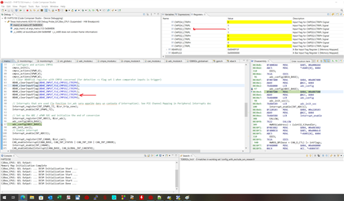
Damien

void cmpss_init()
{
    // Enable CMPSS and configure the negative input signal to come from the DAC
    CMPSS_enableModule(CMPSS1_BASE);
    CMPSS_enableModule(CMPSS2_BASE);
    CMPSS_enableModule(CMPSS3_BASE);
    CMPSS_enableModule(CMPSS4_BASE);

    // Use VDDA as the reference for the DAC and set DAC value to midpoint for arbitrary reference.
    CMPSS_configDAC(CMPSS1_BASE, CMPSS_DACREF_VDDA);
    CMPSS_configDAC(CMPSS2_BASE, CMPSS_DACREF_VDDA);
    CMPSS_configDAC(CMPSS3_BASE, CMPSS_DACREF_VDDA);
    CMPSS_configDAC(CMPSS4_BASE, CMPSS_DACREF_VDDA);

    // To use CMP1_HP2 pin A6 for MU_TRAC_BATT_PCH
    ASysCtl_selectCMPHPMux(ASYSCTL_CMPHPMUX_SELECT_1, 2);
    // To use CMP1_LP3 pin A15/C7 for MU_FUEL_CELL_PCH
    ASysCtl_selectCMPLPMux(ASYSCTL_CMPLPMUX_SELECT_1, 3);
    // To use CMP3_HP1 pin A5/C2 for MI_L_W
    ASysCtl_selectCMPHPMux(ASYSCTL_CMPHPMUX_SELECT_3, 1);
    // To use CMP2_HP1 pin A12/C1 for MI_L_U
    ASysCtl_selectCMPHPMux(ASYSCTL_CMPHPMUX_SELECT_2, 1);
    // To use CMP2_LP4 pin A8/C11 for MI_L_V
    ASysCtl_selectCMPLPMux(ASYSCTL_CMPLPMUX_SELECT_2, 4);
    // To use CMP4_HP1 pin A7/C3 for MI_TRAC_BATT
    ASysCtl_selectCMPHPMux(ASYSCTL_CMPHPMUX_SELECT_4, 1);

    // Configure the output signals. Both CTRIPH will be fed by the asynchronous comparator output.
    //1
    THRESHOLD_MU_TRAC_BATT_PCH_DIGITAL = (THRESHOLD_MU_TRAC_BATT_PCH * 8.2 * 0.000332 * ADC_RESOLUTION) / FULL_SCALE;
    CMPSS_configHighComparator(CMPSS1_BASE, CMPSS_INSRC_DAC);                   // Threshold drive by GPIO or input DAC
    CMPSS_setDACValueHigh(CMPSS1_BASE, THRESHOLD_MU_TRAC_BATT_PCH_DIGITAL);     // Define threshold associated
    CMPSS_configOutputsHigh(CMPSS1_BASE, CMPSS_TRIP_SYNC_COMP);                 // Set output comparator (synchronous or asynchronous)
    //2
    THRESHOLD_MU_FUEL_CELL_PCH_DIGITAL = (THRESHOLD_MU_FUEL_CELL_PCH * 8.2 * 0.000332 * ADC_RESOLUTION) / FULL_SCALE;
    CMPSS_configLowComparator(CMPSS1_BASE, CMPSS_INSRC_DAC);                    // Threshold drive by GPIO or input DAC
    CMPSS_setDACValueLow(CMPSS1_BASE, THRESHOLD_MU_FUEL_CELL_PCH_DIGITAL);      // Define threshold associated
    CMPSS_configOutputsLow(CMPSS1_BASE, CMPSS_TRIP_SYNC_COMP);                  // Set output comparator (synchronous or asynchronous)

    // Configure the output signals. Both CTRIPH will be fed by the asynchronous comparator output.
    //1
    THRESHOLD_MI_L_U_DIGITAL = (((THRESHOLD_MI_L_U * 0.625 / 200) + REF_MI_H_2V5) * ADC_RESOLUTION) / FULL_SCALE;
    CMPSS_configHighComparator(CMPSS2_BASE, CMPSS_INSRC_DAC);                   // Threshold drive by GPIO or input DAC
    CMPSS_setDACValueHigh(CMPSS2_BASE, THRESHOLD_MI_L_U_DIGITAL);               // Define threshold associated
    CMPSS_configOutputsHigh(CMPSS2_BASE, CMPSS_TRIP_SYNC_COMP);                 // Set output comparator (synchronous or asynchronous)

    //2
    THRESHOLD_MI_L_V_DIGITAL = (((THRESHOLD_MI_L_V * 0.625 / 200) + REF_MI_H_2V5) * ADC_RESOLUTION) / FULL_SCALE;
    CMPSS_configLowComparator(CMPSS2_BASE, CMPSS_INSRC_DAC);                    // Threshold drive by GPIO or input DAC
    CMPSS_setDACValueLow(CMPSS2_BASE, THRESHOLD_MI_L_V_DIGITAL);                // Define threshold associated
    CMPSS_configOutputsLow(CMPSS2_BASE, CMPSS_TRIP_SYNC_COMP);                  // Set output comparator (synchronous or asynchronous)

    // Configure the output signals. Both CTRIPH will be fed by the asynchronous comparator output.
    //1
    THRESHOLD_MI_L_W_DIGITAL = (((THRESHOLD_MI_L_W * 0.625 / 200) + REF_MI_H_2V5) * ADC_RESOLUTION) / FULL_SCALE;
    CMPSS_configHighComparator(CMPSS3_BASE, CMPSS_INSRC_DAC);                   // Threshold drive by GPIO or input DAC
    CMPSS_setDACValueHigh(CMPSS3_BASE, THRESHOLD_MI_L_W_DIGITAL);               // Define threshold associated
    CMPSS_configOutputsHigh(CMPSS3_BASE, CMPSS_TRIP_SYNC_COMP);                 // Set output comparator (synchronous or asynchronous)

    // Configure the output signals. Both CTRIPH will be fed by the asynchronous comparator output.
    //1
    THRESHOLD_MI_TRAC_BATT_DIGITAL = ((((THRESHOLD_MI_TRAC_BATT * 2 * 301) / 100000) + REF_MI_BT_1V5) * ADC_RESOLUTION) / FULL_SCALE;
    CMPSS_configHighComparator(CMPSS4_BASE, CMPSS_INSRC_DAC);                   // Threshold drive by GPIO or input DAC
    CMPSS_setDACValueHigh(CMPSS4_BASE, THRESHOLD_MI_TRAC_BATT_DIGITAL);         // Define threshold associated
    CMPSS_configOutputsHigh(CMPSS4_BASE, CMPSS_TRIP_SYNC_COMP);                 // Set output comparator (synchronous or asynchronous)

    // Configure TRIP4 to be CTRIP1H using the ePWM X-BAR. Attach CMPSS output to TRIPINx via EPWMXBAR module
    XBAR_setEPWMMuxConfig(XBAR_TRIP4, XBAR_EPWM_MUX00_CMPSS1_CTRIPH);
    XBAR_setEPWMMuxConfig(XBAR_TRIP5, XBAR_EPWM_MUX01_CMPSS1_CTRIPL);
    XBAR_setEPWMMuxConfig(XBAR_TRIP7, XBAR_EPWM_MUX04_CMPSS3_CTRIPH);
    XBAR_setEPWMMuxConfig(XBAR_TRIP8, XBAR_EPWM_MUX02_CMPSS2_CTRIPH);
    XBAR_setEPWMMuxConfig(XBAR_TRIP9, XBAR_EPWM_MUX03_CMPSS2_CTRIPL);
    XBAR_setEPWMMuxConfig(XBAR_TRIP10, XBAR_EPWM_MUX06_CMPSS4_CTRIPH);

    // See the ePWM X-BAR Mux configuration table, see Crossbar(X-BAR) doc for more informations
    XBAR_enableEPWMMux(XBAR_TRIP4, XBAR_MUX00);
    XBAR_enableEPWMMux(XBAR_TRIP5, XBAR_MUX01);
    XBAR_enableEPWMMux(XBAR_TRIP7, XBAR_MUX04);
    XBAR_enableEPWMMux(XBAR_TRIP8, XBAR_MUX02);
    XBAR_enableEPWMMux(XBAR_TRIP9, XBAR_MUX03);
    XBAR_enableEPWMMux(XBAR_TRIP10, XBAR_MUX06);
}

void cmpss_actions(uint32_t base)
{
    // Configure ePWMx to output low on TZx TRIP
    EPWM_setTripZoneAction(base, EPWM_TZ_ACTION_EVENT_TZA, EPWM_TZ_ACTION_LOW);
    EPWM_setTripZoneAction(base, EPWM_TZ_ACTION_EVENT_TZB, EPWM_TZ_ACTION_LOW);

    // Trigger event when DCBH is high
    EPWM_setTripZoneDigitalCompareEventCondition(base, EPWM_TZ_DC_OUTPUT_B1, EPWM_TZ_EVENT_DCXH_HIGH);

    // Configure DCBH to use TRIP4 as an input
    EPWM_enableDigitalCompareTripCombinationInput(base, EPWM_DC_COMBINATIONAL_TRIPIN4, EPWM_DC_TYPE_DCBH);
    EPWM_enableDigitalCompareTripCombinationInput(base, EPWM_DC_COMBINATIONAL_TRIPIN5, EPWM_DC_TYPE_DCBH);
    EPWM_enableDigitalCompareTripCombinationInput(base, EPWM_DC_COMBINATIONAL_TRIPIN7, EPWM_DC_TYPE_DCBH);
    EPWM_enableDigitalCompareTripCombinationInput(base, EPWM_DC_COMBINATIONAL_TRIPIN8, EPWM_DC_TYPE_DCBH);
    EPWM_enableDigitalCompareTripCombinationInput(base, EPWM_DC_COMBINATIONAL_TRIPIN9, EPWM_DC_TYPE_DCBH);
    EPWM_enableDigitalCompareTripCombinationInput(base, EPWM_DC_COMBINATIONAL_TRIPIN10, EPWM_DC_TYPE_DCBH);

    // Enable DCB as OST
    EPWM_enableTripZoneSignals(base, EPWM_TZ_SIGNAL_DCBEVT1);

    // Clear trip flags
    EPWM_clearTripZoneFlag(base, EPWM_TZ_FLAG_DCBEVT1);
}
#include "cmpss_module.h"
#include "device.h"
#include "adc_module.h"
#include "epwm_module.h"
#include "tripzone_module.h"
#include "can_module.h"
#include "monitoring.h"
#include "sm_global.h"
#include "contactor.h"
#include "timer.h"

void main(void)
{
    // Initialize device clock and peripherals
    Device_init();

    // Disable pin locks and enable internal pullups.
    Device_initGPIO();

    // Initialize PIE and clear PIE registers. Disables CPU interrupts.
    Interrupt_initModule();

    // Initialize the PIE vector table with pointers to the shell Interrupt Service Routines (ISR).
    Interrupt_initVectorTable();

    trip_zone_config();

    gpio_precharge_init();

    gpio_coldplate_init();

    can_init();

    // Initialization timer for ISR TX_CAN
    timer_cpu_init(CPUTIMER0_BASE);
    // Initialization timer for STEP_START_TIMER precharge
    timer_cpu_init(CPUTIMER1_BASE);
    // Initialization timer for monitoring parameters
    timer_cpu_init(CPUTIMER2_BASE);

    // Timer for CAN communication Interrupt all of (us) 10ms
    timer_cpu_config(CPUTIMER0_BASE, DEVICE_SYSCLK_FREQ, 10000);
    // Timer for STEP_START_TIMER precharge all of (us) PARAM_T_PL_US
    config_cpu_timer(CPUTIMER1_BASE);
    // Timer for CAN all of (us) 10ms
    config_cpu_timer(CPUTIMER2_BASE);

    Interrupt_register(INT_TIMER0, &isr_timer);
    CPUTimer_enableInterrupt(CPUTIMER0_BASE);
    Interrupt_enable(INT_TIMER0);
    // Start timer for interrupt CAN (to send frames)
    CPUTimer_startTimer(CPUTIMER0_BASE);
    // Start timer for precharge step (to measure precharge voltage when timer is reached)
    CPUTimer_startTimer(CPUTIMER1_BASE);
    // Start timer for monitoring
    CPUTimer_startTimer(CPUTIMER2_BASE);

    // Disable sync and clock to PWM
    SysCtl_disablePeripheral(SYSCTL_PERIPH_CLK_TBCLKSYNC);

    EALLOW;
    //EPWM1
    GPIO_setPinConfig(GPIO_0_EPWM1_A);
    GPIO_setPinConfig(GPIO_1_EPWM1_B);
    //EPWM2
    GPIO_setPinConfig(GPIO_41_EPWM2_A);
    GPIO_setPinConfig(GPIO_40_EPWM2_B);
    //EPWM4
    GPIO_setPinConfig(GPIO_22_EPWM4_A);
    GPIO_setPinConfig(GPIO_7_EPWM4_B);
    EDIS;

    epwm_init(SPWM_U, 0);
    epwm_init(SPWM_V, EPWM_PHI);
    epwm_init(SPWM_W, EPWM_PHI << 1);

    // Configure and actions CMPSS
    cmpss_init();
    cmpss_actions(SPWM_U);
    cmpss_actions(SPWM_V);
    cmpss_actions(SPWM_W);
    // Clear XBARFLG1 register with CMPSS concerned (for detection => flag set 1 when comparator inputs is trigger)
    XBAR_clearInputFlag(XBAR_INPUT_FLG_CMPSS1_CTRIPH);
    XBAR_clearInputFlag(XBAR_INPUT_FLG_CMPSS1_CTRIPL);
    XBAR_clearInputFlag(XBAR_INPUT_FLG_CMPSS2_CTRIPH);
    XBAR_clearInputFlag(XBAR_INPUT_FLG_CMPSS2_CTRIPL);
    XBAR_clearInputFlag(XBAR_INPUT_FLG_CMPSS3_CTRIPH);
    XBAR_clearInputFlag(XBAR_INPUT_FLG_CMPSS4_CTRIPH);

    // Interrupts that are used (la fonction isr_adc sera appelée dans un contexte d'interruption). See PIE Channel Mapping in Peripheral Interrupts doc
    Interrupt_register(INT_EPWM1_TZ, &isr_trip_zone);
    Interrupt_enable(INT_EPWM1_TZ);

    // Set up the ADC / ePWM SOC and initialize the end of conversion
    Interrupt_register(INT_ADCC1, &isr_adc);
    adc_config(ADCA_BASE);
    adc_config(ADCC_BASE);
    adc_init_soc();
    // Enable interrupt
    Interrupt_enable(INT_ADCC1);

    Interrupt_register(INT_CANA0, &isr_can);
    CAN_enableInterrupt(CANA_BASE, CAN_INT_STATUS | CAN_INT_IE0 | CAN_INT_ERROR);
    Interrupt_enable(INT_CANA0);
    CAN_enableGlobalInterrupt(CANA_BASE, CAN_GLOBAL_INT_CANINT0);

    // Enable sync and clock to PWM
    SysCtl_enablePeripheral(SYSCTL_PERIPH_CLK_TBCLKSYNC);

    // Start CAN module operations
    CAN_startModule(CANA_BASE);

    // Enable Global Interrupt (INTM) and realtime interrupt (DBGM)
    EINT;
    ERTM;

    GPIO_setPinConfig(GPIO_14_GPIO14); // toggle pin for debug
    GPIO_setDirectionMode(14, GPIO_DIR_MODE_OUT);
    GPIO_setPadConfig(14, GPIO_PIN_TYPE_STD);
    GPIO_writePin(14, 0);

    GPIO_setPinConfig(GPIO_15_GPIO15); // toggle pin for debug
    GPIO_setDirectionMode(15, GPIO_DIR_MODE_OUT);
    GPIO_setPadConfig(15, GPIO_PIN_TYPE_STD);
    GPIO_writePin(15, 0);

    GPIO_setPinConfig(GPIO_16_GPIO16); // toggle pin for debug
    GPIO_setDirectionMode(16, GPIO_DIR_MODE_OUT);
    GPIO_setPadConfig(16, GPIO_PIN_TYPE_STD);
    GPIO_writePin(16, 0);

    GPIO_setPinConfig(GPIO_6_GPIO6); // toggle pin for debug
    GPIO_setDirectionMode(6, GPIO_DIR_MODE_OUT);
    GPIO_setPadConfig(6, GPIO_PIN_TYPE_STD);
    GPIO_writePin(6, 0);

    while(1)
    {
        monitoring_hysteresis(&mu_trac_batt_ovp, XBAR_INPUT_FLG_CMPSS1_CTRIPH, &MU_TRAC_BATT_PCH_FLT, &mu_trac_batt_state);
        //monitoring_hysteresis(&mu_fuel_cell_ovp, XBAR_INPUT_FLG_CMPSS1_CTRIPL, &MU_FUEL_CELL_PCH_FLT, &mu_fuel_cell_state);
        //monitoring_hysteresis(&mi_l_u_ocp, XBAR_INPUT_FLG_CMPSS2_CTRIPH, &MI_L_U_FLT, &mi_l_u_state);
        //monitoring_hysteresis(&mi_l_v_ocp, XBAR_INPUT_FLG_CMPSS2_CTRIPL, &MI_L_V_FLT, &mi_l_v_state);
        //monitoring_hysteresis(&mi_l_w_ocp, XBAR_INPUT_FLG_CMPSS3_CTRIPH, &MI_L_W_FLT, &mi_l_w_state);

        // Slow monitoring
        detection_coldplate(cold_plate_pin, &cold_plate_detect, &cold_plate_state_error);
        // First parameter is a structure input and the second is a global pointer to transmit to isr_timer (CAN)
        detection_contactor(&k_line_batt, &k_line_batt_state_error);
        detection_contactor(&k_line_fuel_cell, &k_line_fc_state_error);
        detection_contactor(&k_pl_batt, &k_pl_batt_state_error);
        detection_contactor(&k_pl_fuel_cell, &k_pl_fc_state_error);

        sm_main();

        // Wait while eWPM4 causes conversion and if trip zone is set shoot down ePWM
        // Trip flag is set when CTRIP signal is asserted
        if((EPWM_getTripZoneFlagStatus(SPWM_U) & EPWM_TZ_FLAG_DCBEVT1) != 0U || (EPWM_getTripZoneFlagStatus(SPWM_V) & EPWM_TZ_FLAG_DCBEVT1) != 0U || (EPWM_getTripZoneFlagStatus(SPWM_W) & EPWM_TZ_FLAG_DCBEVT1) != 0U)
        {
            // Clear trip flags
            EPWM_clearTripZoneFlag(SPWM_U, EPWM_TZ_FLAG_DCBEVT1 | EPWM_TZ_FLAG_OST);
            EPWM_clearTripZoneFlag(SPWM_V, EPWM_TZ_FLAG_DCBEVT1 | EPWM_TZ_FLAG_OST);
            EPWM_clearTripZoneFlag(SPWM_W, EPWM_TZ_FLAG_DCBEVT1 | EPWM_TZ_FLAG_OST);
        }
    }
}

  • Hi Damien,

    Thank you for posting your question. I am looking into this and will provide a response by tomorrow.

    Best Regards,

    Marlyn

  • Hi Damien,

    And by looking at the documentation on the Digital compare submodule I think I can read this trigger information in the XbarRegs.XBARFLG1.bit register.
    Is this correct?

    Yes, that is correct. Another way to check the trip status of the CMPSS is to read the COMPSTS of the CMPSS directly. Can you check COMPSTS and let us know what it shows?

    Is it normal that at initialization the bits of this register for the comparators are 1?

    Yes, this is quite normal. Checking statuses during initialization is not advisable since the various modules are powering up and not stabilized yet. Best way is to add a delay after initialization code is complete, clear the status flags and then check.

    Should I use the function XBAR_clearInputFlag(XBAR_INPUT_FLG_CMPSSx) only to set them to 0. It seems to work at initialization in my code (I have in some cases an output that stays high at initialization I mean).

    I can't explain this either?

    See above response.

    On the other hand when I trigger the CMPSS1 for example I can't reset it afterwards in my infinite loop, why?

    How are you triggering and clearing CMPSS1?

    The bit in the register XbarRegs.XBARFLG1.bit. remains at 1. I use the function XBAR_getInputFlagStatus(x) to know which comparator was triggered.

    At the init, I want to reset CMPSS outputs via XBAR_clearInputFlag, and I have a problem one or two output is at level high after the reset function (see the screenshot).

    You need to add a delay after cmpss initialization code is complete. The cmpss has a power up time. 10ms delay should be sufficient.

  • Hi Frank,

    Thanks for your reply it help me in my understanding.

    I've a question : 

    I have signals that trigger my trip zone via InputXbar and others that use CMPSS so they go through EPWMXbar.

    I was using these signals without interrupting the cutoff of my ePWMs. Now I want to use them with interrupt. I configured my interrupts using INT_EPWM2_TZ => signals coming from inputXbar and INT_EPWM1_TZ for CMPSS. The interrupt goes well but does not restart after user acknowledgement.
    The flag in the XBARFLG1 register is reset to 0 using XBAR_clearInputFlag() but the TZEINT register is not reset to 0, is this the cause ?

    I use this function EPWM_clearTripZoneFlag which theoretically acts on the TZEINT register but it does not work.
    Did I forget a step ?

    In expectation

    Thanks

    Damien

    You can see an extract of my code :

    if(mi_l_u_state == PROTECTION_DETECTED)
        {
            step_global = STATE_GLOBAL_FAULT;
            step_fault = STEP_CONVERTER_INH;
            if(ack_inh_converter == 1)
            {
                step_fault = STEP_OPEN_K_LINE_FC_CONTACTOR;
                if(ack_open_k_line_fc == 1)
                {
                    step_fault = STEP_NONE;
                    ack_inh_converter = 0;
                    ack_open_k_line_fc = 0;
                    if(ack_ok == 1)
                    {
                        // Clear XBARFLG1 and TZCLR register
                        XBAR_clearInputFlag(XBAR_INPUT_FLG_CMPSS2_CTRIPH);
                        EPWM_clearTripZoneFlag(SPWM_U, EPWM_TZ_FLAG_DCBEVT1);
                        EPWM_clearTripZoneFlag(SPWM_V, EPWM_TZ_FLAG_DCBEVT1);
                        EPWM_clearTripZoneFlag(SPWM_W, EPWM_TZ_FLAG_DCBEVT1);
                        // ePWM are set ON with the duty cycle desire.
                        epwm_cmpa = epwm_get_cmpa_from_dutycyle(SPWM_U, epwm_dutycyle);
                        EPWM_setCounterCompareValue(SPWM_U, EPWM_COUNTER_COMPARE_A, epwm_cmpa);
                        EPWM_setCounterCompareValue(SPWM_V, EPWM_COUNTER_COMPARE_A, epwm_cmpa);
                        EPWM_setCounterCompareValue(SPWM_W, EPWM_COUNTER_COMPARE_A, epwm_cmpa);
                        step_global = STATE_GLOBAL_STANDBY;
                        mi_l_u_state = PROTECTION_OK;
                    }
                }
            }
        }

        epwm_init(SPWM_U, 0);
        epwm_init(SPWM_V, EPWM_PHI);
        epwm_init(SPWM_W, EPWM_PHI << 1);
    
        // Configure and actions CMPSS
        cmpss_init();
        cmpss_actions(SPWM_U);
        cmpss_actions(SPWM_V);
        cmpss_actions(SPWM_W);
        // Clear XBARFLG1 register with CMPSS concerned (for detection => flag set 1 when comparator inputs is trigger). Add delay after reset and then clear status flag (power up time).
        DEVICE_DELAY_US(10000);
        XBAR_clearInputFlag(XBAR_INPUT_FLG_CMPSS1_CTRIPH);
        XBAR_clearInputFlag(XBAR_INPUT_FLG_CMPSS1_CTRIPL);
        XBAR_clearInputFlag(XBAR_INPUT_FLG_CMPSS2_CTRIPH);
        XBAR_clearInputFlag(XBAR_INPUT_FLG_CMPSS2_CTRIPL);
        XBAR_clearInputFlag(XBAR_INPUT_FLG_CMPSS3_CTRIPH);
        XBAR_clearInputFlag(XBAR_INPUT_FLG_CMPSS4_CTRIPH);
    
        // Interrupts that are used. See PIE Channel Mapping in Peripheral Interrupts doc
        // DRV to trip zone
        Interrupt_register(INT_EPWM2_TZ, &isr_return_driver);
        Interrupt_enable(INT_EPWM2_TZ);
        // CMPSS to trip zone
        Interrupt_register(INT_EPWM1_TZ, &isr_cmpss);
        Interrupt_enable(INT_EPWM1_TZ);
    

  • Below is my configuration for the trip zone for GPIO=>InputXbar

    void trip_zone_config(void)
    {
    // DRV-U signals to trip zone
    GPIO_setPinConfig(GPIO_45_GPIO45);
    GPIO_setDirectionMode(45, GPIO_DIR_MODE_IN);
    GPIO_setPadConfig(45, GPIO_PIN_TYPE_STD);

    // DRV-V signals to trip zone
    GPIO_setPinConfig(GPIO_5_GPIO5);
    GPIO_setDirectionMode(5, GPIO_DIR_MODE_IN);
    GPIO_setPadConfig(5, GPIO_PIN_TYPE_STD);

    // DRV-W signals to trip zone
    GPIO_setPinConfig(GPIO_9_GPIO9);
    GPIO_setDirectionMode(9, GPIO_DIR_MODE_IN);
    GPIO_setPadConfig(9, GPIO_PIN_TYPE_STD);

    XBAR_setInputPin(INPUTXBAR_BASE, XBAR_INPUT1, 45);
    XBAR_setInputPin(INPUTXBAR_BASE, XBAR_INPUT2, 5);
    XBAR_setInputPin(INPUTXBAR_BASE, XBAR_INPUT3, 9);

    // Enable TZx as one shot trip sources
    // TZ1 for DRV_U
    EPWM_enableTripZoneSignals(SPWM_U, EPWM_TZ_SIGNAL_OSHT1);
    EPWM_enableTripZoneSignals(SPWM_V, EPWM_TZ_SIGNAL_OSHT1);
    EPWM_enableTripZoneSignals(SPWM_W, EPWM_TZ_SIGNAL_OSHT1);

    // TZ2 for DRV_V
    EPWM_enableTripZoneSignals(SPWM_U, EPWM_TZ_SIGNAL_OSHT2);
    EPWM_enableTripZoneSignals(SPWM_V, EPWM_TZ_SIGNAL_OSHT2);
    EPWM_enableTripZoneSignals(SPWM_W, EPWM_TZ_SIGNAL_OSHT2);

    // TZ3 for DRV_W
    EPWM_enableTripZoneSignals(SPWM_U, EPWM_TZ_SIGNAL_OSHT3);
    EPWM_enableTripZoneSignals(SPWM_V, EPWM_TZ_SIGNAL_OSHT3);
    EPWM_enableTripZoneSignals(SPWM_W, EPWM_TZ_SIGNAL_OSHT3);

    // Action on TZx
    EPWM_setTripZoneAction(SPWM_U, EPWM_TZ_ACTION_EVENT_TZA, EPWM_TZ_ACTION_HIGH);
    EPWM_setTripZoneAction(SPWM_V, EPWM_TZ_ACTION_EVENT_TZA, EPWM_TZ_ACTION_HIGH);
    EPWM_setTripZoneAction(SPWM_W, EPWM_TZ_ACTION_EVENT_TZA, EPWM_TZ_ACTION_HIGH);

    EPWM_enableTripZoneInterrupt(SPWM_U, EPWM_TZ_INTERRUPT_OST);
    EPWM_enableTripZoneInterrupt(SPWM_V, EPWM_TZ_INTERRUPT_OST);
    EPWM_enableTripZoneInterrupt(SPWM_W, EPWM_TZ_INTERRUPT_OST);
    }

    __interrupt void isr_return_driver(void)
    {
    GPIO_writePin(14, 1);
    DEVICE_DELAY_US(10);
    GPIO_writePin(14, 0);
    // Acknowledge this interrupt to receive more interrupts from group 2
    Interrupt_clearACKGroup(INTERRUPT_ACK_GROUP2);
    }

    Interrupt_register(INT_EPWM2_TZ, &isr_return_driver);
    Interrupt_enable(INT_EPWM2_TZ);
    // CMPSS to trip zone
    Interrupt_register(INT_EPWM1_TZ, &isr_cmpss);
    Interrupt_enable(INT_EPWM1_TZ);

    And configuration for CMPSS:

    void cmpss_actions(uint32_t base)
    {
        // Configure ePWMx to output low on TZx TRIP
        EPWM_setTripZoneAction(base, EPWM_TZ_ACTION_EVENT_TZA, EPWM_TZ_ACTION_LOW);
        EPWM_setTripZoneAction(base, EPWM_TZ_ACTION_EVENT_TZB, EPWM_TZ_ACTION_LOW);
    
        // Trigger event when DCBH is high
        EPWM_setTripZoneDigitalCompareEventCondition(base, EPWM_TZ_DC_OUTPUT_B1, EPWM_TZ_EVENT_DCXH_HIGH);
    
        // Configure DCBH to use TRIP4 as an input
        EPWM_enableDigitalCompareTripCombinationInput(base, EPWM_DC_COMBINATIONAL_TRIPIN4, EPWM_DC_TYPE_DCBH);
        EPWM_enableDigitalCompareTripCombinationInput(base, EPWM_DC_COMBINATIONAL_TRIPIN5, EPWM_DC_TYPE_DCBH);
        EPWM_enableDigitalCompareTripCombinationInput(base, EPWM_DC_COMBINATIONAL_TRIPIN7, EPWM_DC_TYPE_DCBH);
        EPWM_enableDigitalCompareTripCombinationInput(base, EPWM_DC_COMBINATIONAL_TRIPIN8, EPWM_DC_TYPE_DCBH);
        EPWM_enableDigitalCompareTripCombinationInput(base, EPWM_DC_COMBINATIONAL_TRIPIN9, EPWM_DC_TYPE_DCBH);
        EPWM_enableDigitalCompareTripCombinationInput(base, EPWM_DC_COMBINATIONAL_TRIPIN10, EPWM_DC_TYPE_DCBH);
    
        // Enable DCB as DCBEVT1
        EPWM_enableTripZoneSignals(base, EPWM_TZ_SIGNAL_DCBEVT1);
        // Enable interrupt
        EPWM_enableTripZoneInterrupt(SPWM_U, EPWM_TZ_INTERRUPT_DCBEVT1);
        EPWM_enableTripZoneInterrupt(SPWM_V, EPWM_TZ_INTERRUPT_DCBEVT1);
        EPWM_enableTripZoneInterrupt(SPWM_W, EPWM_TZ_INTERRUPT_DCBEVT1);
        // Clear trip flags
        EPWM_clearTripZoneFlag(base, EPWM_TZ_FLAG_DCBEVT1);
    }
    
    __interrupt void isr_cmpss(void)
    {
        GPIO_writePin(15, 1);
        // Acknowledge this interrupt to receive more interrupts from group 2
        DEVICE_DELAY_US(10);
        GPIO_writePin(15, 0);
        Interrupt_clearACKGroup(INTERRUPT_ACK_GROUP2);
    }
    

    I want to generate two independent interrupts : 

    inputXbar => TZ interrupt OST and CMPSS => EpwmXbar => Tripzone => DCBEVT1. It's possible no ? There is a mistake in my code ? Configuration ?

    Can you help me please ?

    Concerning the interrupt table, the names INT_EPWMx_TZ are only names because the action of the trip zone is defined in the configuration, right?
    Here is an extract from a header file
    #define INT_EPWM1_TZ 0x00280201U // 2.1 - ePWM1 Trip Zone Interrupt
    #define INT_EPWM2_TZ 0x00290202U // 2.2 - ePWM2 Trip Zone Interrupt
    #define INT_EPWM3_TZ 0x002A0203U // 2.3 - ePWM3 Trip Zone Interrupt
    #define INT_EPWM4_TZ 0x002B0204U // 2.4 - ePWM4 Trip Zone Interrupt
    #define INT_EPWM5_TZ 0x002C0205U // 2.5 - ePWM5 Trip Zone Interrupt
    #define INT_EPWM6_TZ 0x002D0206U // 2.6 - ePWM6 Trip Zone Interrupt
    #define INT_EPWM7_TZ 0x002E0207U // 2.7 - ePWM7 Trip Zone Interrupt
    Can we shut down several PWM signals on the same interrupt ?

    I am sorry to have created two posts I have questions about both thank you

    Damien

  • Hi Damien,

    In order not to lose track, let's address one issue at a time?

    I was using these signals without interrupting the cutoff of my ePWMs. Now I want to use them with interrupt. I configured my interrupts using INT_EPWM2_TZ => signals coming from inputXbar and INT_EPWM1_TZ for CMPSS. The interrupt goes well but does not restart after user acknowledgement.
    The flag in the XBARFLG1 register is reset to 0 using XBAR_clearInputFlag() but the TZEINT register is not reset to 0, is this the cause ?

    I use this function EPWM_clearTripZoneFlag which theoretically acts on the TZEINT register but it does not work.
    Did I forget a step ?

    I think this is happening because you are not clearing the "INT" field of TZFLG. Until TZFLG.INT is cleared, no further interrupts will be generated. You can also refer to this C2000Ware example which is quite similar to what you are doing -> "C2000Ware_version\driverlib\f28002x\examples\epwm\epwm_ex1_trip_zone.c"

    Once you confirm above is resolved, we can look at your other issue.

  • Hi Frank,

    Thanks for your reply, yes step by step ! Indeed I had forgotten to reset TZFLG register by TZCLR with this function at the end of my first interrupt for trip zone : EPWM_clearTripZoneFlag(SPWM_U, (EPWM_TZ_INTERRUPT | EPWM_TZ_FLAG_CBC))

    It work fine for this part it shut down my ePWM when GPIO set to 0 I enter in my interrupt to get a screen shot at the time for event log recording in my project.

    The TZ signals do not have to go through the digital compare module ? That's how I understand it and I have configured it so that the DCxEVTx events are not activated? And to have two independent interrupts between inputXbar and EpwmXbar, I want to configure only my signals from ePWMXbar on these events. Is this the right way to do it? I use InputXbar signals for driver feedback and CMPSS for different security (Over voltage ...).
    I don't have very clear ideas about this Digital compare module even if I look at the documentation.

    For EPwmXbar signals, I must use DCBEVTx only ? If I understand correctly DC Submodule. So why it doesn't work with my configuration ? You can see my code :

    void cmpss_actions(uint32_t base)
    {
        // Configure ePWMx to output low on TZx TRIP
        EPWM_setTripZoneAction(base, EPWM_TZ_ACTION_EVENT_TZA, EPWM_TZ_ACTION_LOW);
        EPWM_setTripZoneAction(base, EPWM_TZ_ACTION_EVENT_TZB, EPWM_TZ_ACTION_LOW);
    
        // Trigger event when DCBH is high
        EPWM_setTripZoneDigitalCompareEventCondition(base, EPWM_TZ_DC_OUTPUT_B1, EPWM_TZ_EVENT_DCXH_HIGH);
    
        // Configure DCBH to use TRIPINx as an input
        EPWM_enableDigitalCompareTripCombinationInput(base, EPWM_DC_COMBINATIONAL_TRIPIN4, EPWM_DC_TYPE_DCBH);
        EPWM_enableDigitalCompareTripCombinationInput(base, EPWM_DC_COMBINATIONAL_TRIPIN5, EPWM_DC_TYPE_DCBH);
        EPWM_enableDigitalCompareTripCombinationInput(base, EPWM_DC_COMBINATIONAL_TRIPIN7, EPWM_DC_TYPE_DCBH);
        EPWM_enableDigitalCompareTripCombinationInput(base, EPWM_DC_COMBINATIONAL_TRIPIN8, EPWM_DC_TYPE_DCBH);
        EPWM_enableDigitalCompareTripCombinationInput(base, EPWM_DC_COMBINATIONAL_TRIPIN9, EPWM_DC_TYPE_DCBH);
        EPWM_enableDigitalCompareTripCombinationInput(base, EPWM_DC_COMBINATIONAL_TRIPIN10, EPWM_DC_TYPE_DCBH);
    
        // Enable DCB as DCBEVT1
        EPWM_enableTripZoneSignals(base, EPWM_TZ_SIGNAL_DCBEVT2);
        // Enable interrupt
        EPWM_enableTripZoneInterrupt(base, EPWM_TZ_INTERRUPT_DCBEVT2);
        // Clear trip flags
        //EPWM_clearTripZoneFlag(base, EPWM_TZ_FLAG_DCBEVT2);
    }
    
    // Interrupt to have a photo for event log
    __interrupt void isr_cmpss(void)
    {
        GPIO_writePin(15, 1);
    
        // Acknowledge this interrupt to receive more interrupts from group 2
        GPIO_writePin(15, 0);
        EPWM_clearTripZoneFlag(SPWM_U, (EPWM_TZ_INTERRUPT | EPWM_TZ_INTERRUPT_DCBEVT2));
        EPWM_clearTripZoneFlag(SPWM_V, (EPWM_TZ_INTERRUPT | EPWM_TZ_INTERRUPT_DCBEVT2));
        EPWM_clearTripZoneFlag(SPWM_W, (EPWM_TZ_INTERRUPT | EPWM_TZ_INTERRUPT_DCBEVT2));
        Interrupt_clearACKGroup(INTERRUPT_ACK_GROUP2);
    }
    oid trip_zone_config(void)
    {
        // DRV-U signals to trip zone
        GPIO_setPinConfig(GPIO_45_GPIO45);
        GPIO_setDirectionMode(45, GPIO_DIR_MODE_IN);
        GPIO_setPadConfig(45, GPIO_PIN_TYPE_STD);
    
        // DRV-V signals to trip zone
        GPIO_setPinConfig(GPIO_5_GPIO5);
        GPIO_setDirectionMode(5, GPIO_DIR_MODE_IN);
        GPIO_setPadConfig(5, GPIO_PIN_TYPE_STD);
    
        // DRV-W signals to trip zone
        GPIO_setPinConfig(GPIO_9_GPIO9);
        GPIO_setDirectionMode(9, GPIO_DIR_MODE_IN);
        GPIO_setPadConfig(9, GPIO_PIN_TYPE_STD);
    
        XBAR_setInputPin(INPUTXBAR_BASE, XBAR_INPUT1, 45);
        XBAR_setInputPin(INPUTXBAR_BASE, XBAR_INPUT2, 5);
        XBAR_setInputPin(INPUTXBAR_BASE, XBAR_INPUT3, 9);
    
        // Enable TZx as cycle by cycle trip sources
        // TZ1 for DRV_U
        EPWM_enableTripZoneSignals(SPWM_U, EPWM_TZ_SIGNAL_CBC1);
        EPWM_enableTripZoneSignals(SPWM_V, EPWM_TZ_SIGNAL_CBC1);
        EPWM_enableTripZoneSignals(SPWM_W, EPWM_TZ_SIGNAL_CBC1);
    
        // TZ2 for DRV_V
        EPWM_enableTripZoneSignals(SPWM_U, EPWM_TZ_SIGNAL_CBC2);
        EPWM_enableTripZoneSignals(SPWM_V, EPWM_TZ_SIGNAL_CBC2);
        EPWM_enableTripZoneSignals(SPWM_W, EPWM_TZ_SIGNAL_CBC2);
    
        // TZ3 for DRV_W
        EPWM_enableTripZoneSignals(SPWM_U, EPWM_TZ_SIGNAL_CBC3);
        EPWM_enableTripZoneSignals(SPWM_V, EPWM_TZ_SIGNAL_CBC3);
        EPWM_enableTripZoneSignals(SPWM_W, EPWM_TZ_SIGNAL_CBC3);
    
        // Action on TZx
        EPWM_setTripZoneAction(SPWM_U, EPWM_TZ_ACTION_EVENT_TZA, EPWM_TZ_ACTION_HIGH);
        EPWM_setTripZoneAction(SPWM_V, EPWM_TZ_ACTION_EVENT_TZA, EPWM_TZ_ACTION_HIGH);
        EPWM_setTripZoneAction(SPWM_W, EPWM_TZ_ACTION_EVENT_TZA, EPWM_TZ_ACTION_HIGH);
    
        EPWM_enableTripZoneInterrupt(SPWM_U, EPWM_TZ_INTERRUPT_CBC);
        EPWM_enableTripZoneInterrupt(SPWM_V, EPWM_TZ_INTERRUPT_CBC);
        EPWM_enableTripZoneInterrupt(SPWM_W, EPWM_TZ_INTERRUPT_CBC);
    }
    
    __interrupt void isr_return_driver(void)
    {
        GPIO_writePin(14, 1);
        DEVICE_DELAY_US(10);
        GPIO_writePin(14, 0);
        //Clear the flags, we will continue to take this interrupt until the TZ pin goes high.
        EPWM_clearTripZoneFlag(SPWM_U, (EPWM_TZ_INTERRUPT | EPWM_TZ_FLAG_CBC));
        EPWM_clearTripZoneFlag(SPWM_V, (EPWM_TZ_INTERRUPT | EPWM_TZ_FLAG_CBC));
        EPWM_clearTripZoneFlag(SPWM_W, (EPWM_TZ_INTERRUPT | EPWM_TZ_FLAG_CBC));
        // Acknowledge this interrupt to receive more interrupts from group 2
        Interrupt_clearACKGroup(INTERRUPT_ACK_GROUP2);
    }

    Thanks Damien

  • I have made progress on my problem : when I desactive in my main the first interrupt so set only the inputxbar interrupt it's work fine in TZFLG CBC.bit and INT.bit are set when input is set to 0 and reset when input is set to 1 and shutdown ePWM correctly.  Concerned the other ePWMXbar interrupt, I've made a mistake in configuration PWM_setTripZoneDigitalCompareEventCondition : EPWM_TZ_DC_OUTPUT_B1 whereas I use EPWM_TZ_SIGNAL_DCBEVT2.So I change EPWM_TZ_DC_OUTPUT_B2. Now In TZFLG register DCBEVT2 is set to 1 when enter in interrupt and reset after.

    But when EPwmXbar input is set to 0, TZFLG.bit.CBC and  TZFLG.bit.INT are always to 1 why ?

  • Hi Damien,

    Do you have a high level diagram of your system? If not, is this something you can create and provide to us? I think this will make it easier for us to bridge the gap between what you have in mind and how you are implementing the code.

  • Hi 

    I will be able to do this for you immediately tonight, it is complicated. To enlighten you on my system it is a high power converter I connected the returns of driver of semiconductors on the inputs TZ1 to TZ3 and safeties over voltage for example on the CMPSS. I isolated the two interrupts independently, it works well, the register TZFLG.bit.CBC and TZFLG.bit.INT are at 1 when I activate only the interrupt linked to the signals TZ1 to TZ3 and then reset to 0 when the output disables the TZ signals. For the interrupts linked to the CMPSS, I have configured the CMPSS with DCBEVT2 and in the register when these are triggered only and not TZ, the bits TZFLG.bit.DCBEVT2 and TZFLG.bit.CBC are active. You will find a part of my code in our previous exchanges.
    To summarize my system: I use interrupts only to obtain an event log and to have a state of my variables during a fault.
    It is possible to have two independent interrupts for my signals TZ1 to TZ3 and the signals coming from the EpWmXbar, no?
    Can you help me with my previous questions?

    Thanks
    Damien

  • Hi Damien,

    I will be able to do this for you immediately tonight, it is complicated.

    It doesn't have to be detailed. Just a high level overview of connections.

    To enlighten you on my system it is a high power converter I connected the returns of driver of semiconductors on the inputs TZ1 to TZ3 and safeties over voltage for example on the CMPSS. I isolated the two interrupts independently, it works well, the register TZFLG.bit.CBC and TZFLG.bit.INT are at 1 when I activate only the interrupt linked to the signals TZ1 to TZ3 and then reset to 0 when the output disables the TZ signals.

    This makes sense.

    For the interrupts linked to the CMPSS, I have configured the CMPSS with DCBEVT2 and in the register when these are triggered only and not TZ, the bits TZFLG.bit.DCBEVT2 and TZFLG.bit.CBC are active. You will find a part of my code in our previous exchanges.

    This also makes sense.

    To summarize my system: I use interrupts only to obtain an event log and to have a state of my variables during a fault.

    Ok. Are you only interested in generating interrupts or are you having these TZ signals shut off the PWM?

    It is possible to have two independent interrupts for my signals TZ1 to TZ3 and the signals coming from the EpWmXbar, no?

    There is one TZ interrupt per EPWM. However you can figure out which TZ caused the trigger through TZCBCFLG and TZOSTFLG registers.

    Responses to your previous questions:

    The TZ signals do not have to go through the digital compare module ?

    Correct. TZ signals don't have to go through the DC module.

    That's how I understand it and I have configured it so that the DCxEVTx events are not activated? And to have two independent interrupts between inputXbar and EpwmXbar, I want to configure only my signals from ePWMXbar on these events. Is this the right way to do it?

    See previous response. There is one TZ interrupt per EPWM but you can always figure out the source of the interrupt through the various flag registers.

  • Ok. Are you only interested in generating interrupts or are you having these TZ signals shut off the PWM?

    Reply : Yes, TZ signals shut off PWM and generate interrupt for event trigger. It's now much clearer to me, it run very well.

    But I have a new question related to this topic, I use CCS studio in real time to visualize registers and variables on debug mode. It run before clear TZFLGCBC register, is it a coincidence ? Because I have an error message : 

    Trouble Reading Register PC:
    (Error -1142 @ 0x0)
    Device blocked debug access because it is currently executing non-debuggable code. Choose 'Rude Retry' to disable polite mode and force the operation.
    (Emulation package 9.4.0.00129)

    I tried several manipulations but nothing conclusive. The mode works if I reset only one flag on the TZFLGCBC register

    If I make this config it doesn't work, why ?

    __interrupt void isr_trip_zone(void)
    {
        GPIO_writePin(14, 1);
    
        // Clear the flags, we will continue to take this interrupt until the TZ pin goes high.
        EPWM_clearTripZoneFlag(SPWM_U, (EPWM_TZ_INTERRUPT | EPWM_TZ_FLAG_CBC | EPWM_TZ_FLAG_DCBEVT2));
        EPWM_clearTripZoneFlag(SPWM_V, (EPWM_TZ_INTERRUPT | EPWM_TZ_FLAG_CBC | EPWM_TZ_FLAG_DCBEVT2));
        EPWM_clearTripZoneFlag(SPWM_W, (EPWM_TZ_INTERRUPT | EPWM_TZ_FLAG_CBC | EPWM_TZ_FLAG_DCBEVT2));
    
        if(EPWM_getCycleByCycleTripZoneFlagStatus(SPWM_U) == EPWM_TZ_CBC_FLAG_1)
        {
            EPWM_clearCycleByCycleTripZoneFlag(SPWM_U ,EPWM_TZ_CBC_FLAG_1);
            EPWM_clearCycleByCycleTripZoneFlag(SPWM_V ,EPWM_TZ_CBC_FLAG_1);
            EPWM_clearCycleByCycleTripZoneFlag(SPWM_W ,EPWM_TZ_CBC_FLAG_1);
        }
        if(EPWM_getCycleByCycleTripZoneFlagStatus(SPWM_U == EPWM_TZ_CBC_FLAG_2))
        {
            EPWM_clearCycleByCycleTripZoneFlag(SPWM_U ,EPWM_TZ_CBC_FLAG_2);
            EPWM_clearCycleByCycleTripZoneFlag(SPWM_V ,EPWM_TZ_CBC_FLAG_2);
            EPWM_clearCycleByCycleTripZoneFlag(SPWM_W ,EPWM_TZ_CBC_FLAG_2);
        }
        if(EPWM_getCycleByCycleTripZoneFlagStatus(SPWM_U == EPWM_TZ_CBC_FLAG_3))
        {
            EPWM_clearCycleByCycleTripZoneFlag(SPWM_U ,EPWM_TZ_CBC_FLAG_3);
            EPWM_clearCycleByCycleTripZoneFlag(SPWM_V ,EPWM_TZ_CBC_FLAG_3);
            EPWM_clearCycleByCycleTripZoneFlag(SPWM_W ,EPWM_TZ_CBC_FLAG_3);
        }
        if(EPWM_getCycleByCycleTripZoneFlagStatus(SPWM_U == EPWM_TZ_CBC_FLAG_DCBEVT2))
        {
            EPWM_clearCycleByCycleTripZoneFlag(SPWM_U ,EPWM_TZ_CBC_FLAG_DCBEVT2);
            EPWM_clearCycleByCycleTripZoneFlag(SPWM_V ,EPWM_TZ_CBC_FLAG_DCBEVT2);
            EPWM_clearCycleByCycleTripZoneFlag(SPWM_W ,EPWM_TZ_CBC_FLAG_DCBEVT2);
        }
        GPIO_writePin(14, 0);
    
        // Acknowledge this interrupt to receive more interrupts from group 2
        Interrupt_clearACKGroup(INTERRUPT_ACK_GROUP2);
    }
    

    Thank you for your feedback,

    Damien

  • Damien,

    Reply : Yes, TZ signals shut off PWM and generate interrupt for event trigger. It's now much clearer to me, it run very well.

    Ok, so this part is resolved now?

    But I have a new question related to this topic, I use CCS studio in real time to visualize registers and variables on debug mode. It run before clear TZFLGCBC register, is it a coincidence ? Because I have an error message : 

    Trouble Reading Register PC:
    (Error -1142 @ 0x0)
    Device blocked debug access because it is currently executing non-debuggable code. Choose 'Rude Retry' to disable polite mode and force the operation.
    (Emulation package 9.4.0.00129)

    I tried several manipulations but nothing conclusive. The mode works if I reset only one flag on the TZFLGCBC register

    If I make this config it doesn't work, why ?

    I'm not quite clear on this question. What runs before "clear TZFLGCBC register"? Can you outline the exact steps you executed that resulted in this error?

  • Hi Frank,

    Thanks for your reply. Yes the first part is resolved now it's clear for me.

    I don't have the problem any more by activating the real time mode I didn't understand the cause I leave aside, I continue my development I will return on it later if the problem returns. Thank you for your explanations.

    Damien

  • Hi Damien,

    Glad to help. Let us know if you ran into anymore issues.