This thread has been locked.

If you have a related question, please click the "Ask a related question" button in the top right corner. The newly created question will be automatically linked to this question.

TMS320F28388D: Interrupt on SCI-C Rx

Part Number: TMS320F28388D

Hi everyone,

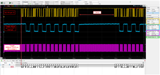
I have a sensor sending data over UART, it is connected to the SCI C pin 13 on my F28388D. The baudrate is 9216000. The data is 28 bytes starting with 0x91:

91 FF FF BC FF FF 8F 00 02 13 00 FF F1 08 FF FC FB 03 FF 5F 00 9F 01 FB 4C 76 47 4A

I am able to see the data coming with my logic analyzer, and I am able to see the data using another program that calls SCI_readCharArray in my main loop. So I know the hardware is OK

To be more efficient I would like to use interrupts to receive the data and put them in a buffer.

I started with the sci_ex2_loopback_interrupts example and replaced the SCI A to SCI C and the pinout of the RX to pin 13.

I also disable the  SCI_enableLoopback and remove the stuff for the TX interrupt that I don't need (receive data only).

I change the clock to get 200Mhz so I am able to get my 921600 baudrate:

in the device.c :

    SysCtl_setLowSpeedClock(SYSCTL_LSPCLK_PRESCALE_1);

and device.h 

#define DEVICE_LSPCLK_FREQ          (DEVICE_SYSCLK_FREQ / 1)

The fifo level expects that 2 elements of data are received before the ISR is hit, but when I run the code it's stay in the loop and the interrupt is never called.

I have one concern, why INTERRUPT_ACK_GROUP9 has been chosen for the Interrupt_clearACKGroup? Might it be an issue using SCI-C?

I attached my project if you want to take a look.

Thank you

sci_ex2_loopback_interrupts.zip

  • Hi,

    Thanks for your question. You are correct that GROUP9 is not the right ACK group to use for SCI-C. Group 9 is for SCI-A and B.

    If using SCI-C, you will need to change to use GROUP8.

    See the PIE Channel Mapping from the TRM below.

    Regards,

    Vince

  • Thank you very much Vince it now enters in the interrupt but only in debug mode or the first time I flash. If I reset or power cycle it stay in the while loop.

    Any idea what would prevent the interrupt to trig?

    I used SCI_FIFO_RX14 to trig the interrupt when the FIFO stored 28 bytes.

    I know it is stuck in my while 1 because I see LED_RED_GPIO28 toggling but not LED_GREEN_GPIO29 that is in the interrupt.

    //###########################################################################
    //
    // FILE:   sci_ex2_loopback_interrupts.c
    //
    // TITLE:  SCI Digital Loop Back with Interrupts.
    //
    //! \addtogroup driver_example_list
    //! <h1> SCI Digital Loop Back with Interrupts </h1>
    //!
    //!  This test uses the internal loop back test mode of the peripheral.
    //!  Other then boot mode pin configuration, no other hardware configuration
    //!  is required. Both interrupts and the SCI FIFOs are used.
    //!
    //!  A stream of data is sent and then compared to the received stream.
    //!  The SCI-A sent data looks like this: \n
    //!  00 01 \n
    //!  01 02 \n
    //!  02 03 \n
    //!  .... \n
    //!  FE FF \n
    //!  FF 00 \n
    //!  etc.. \n
    //!  The pattern is repeated forever.
    //!
    //!  \b Watch \b Variables \n
    //!  - \b sDataA - Data being sent
    //!  - \b rDataA - Data received
    //!  - \b rDataPointA - Keep track of where we are in the data stream.
    //!    This is used to check the incoming data
    //!
    //
    //###########################################################################
    //
    //
    // $Copyright: $
    //###########################################################################
    
    //
    // Included Files
    //
    #include "driverlib.h"
    #include "device.h"
    
    //
    // Globals
    //
    
    //
    // Send data for SCI-C
    //
    uint16_t sDataA[2];
    
    //
    // Received data for SCI-C
    //
    uint16_t rData[28];
    uint16_t ByteReceived =0;
    uint16_t rDatagram[28];
    uint16_t cpt = 0;
    //
    // Used for checking the received data
    //
    uint16_t rDataPointA;
    
    //
    // Function Prototypes
    //
    //__interrupt void scicTXFIFOISR(void);
    __interrupt void scicRXFIFOISR(void);
    void initSCICFIFO(void);
    void error(void);
    
    #define LED_RED_GPIO28 28
    #define LED_GREEN_GPIO29 29
    #define GPIO_DEBUG 31
    //
    // Main
    //
    void main(void)
    {
        uint16_t i;
    
        //
        // Initialize device clock and peripherals
        //
        Device_init();
    
        //
        // Setup GPIO by disabling pin locks and enabling pullups
        //
        Device_initGPIO();
    
        //
        // GPIO28 is the SCI Rx pin.
        //
        GPIO_setMasterCore(DEVICE_GPIO_PIN_SCIRXDC, GPIO_CORE_CPU1);
        GPIO_setPinConfig(DEVICE_GPIO_CFG_SCIRXDC);
        GPIO_setDirectionMode(DEVICE_GPIO_PIN_SCIRXDC, GPIO_DIR_MODE_IN);
        GPIO_setPadConfig(DEVICE_GPIO_PIN_SCIRXDC, GPIO_PIN_TYPE_STD);
        GPIO_setQualificationMode(DEVICE_GPIO_PIN_SCIRXDC, GPIO_QUAL_ASYNC);
    
        // GPIO28 -> LED_RED_GPIO28 Pinmux
        GPIO_setPinConfig(GPIO_28_GPIO28);
        GPIO_setPinConfig(GPIO_29_GPIO29);
        GPIO_setPinConfig(GPIO_31_GPIO31);
    
        //LED_RED_GPIO28 initialization
        GPIO_setDirectionMode(LED_RED_GPIO28, GPIO_DIR_MODE_OUT);
        GPIO_setPadConfig(LED_RED_GPIO28, GPIO_PIN_TYPE_STD);
        GPIO_setMasterCore(LED_RED_GPIO28, GPIO_CORE_CPU1);
        GPIO_setQualificationMode(LED_RED_GPIO28, GPIO_QUAL_SYNC);
    
        //LED_GREEN_GPIO29 initialization
        GPIO_setDirectionMode(LED_GREEN_GPIO29, GPIO_DIR_MODE_OUT);
        GPIO_setPadConfig(LED_GREEN_GPIO29, GPIO_PIN_TYPE_STD);
        GPIO_setMasterCore(LED_GREEN_GPIO29, GPIO_CORE_CPU1);
        GPIO_setQualificationMode(LED_GREEN_GPIO29, GPIO_QUAL_SYNC);
    
        //DEBUG PIN initialization
        GPIO_setDirectionMode(GPIO_DEBUG, GPIO_DIR_MODE_OUT);
        GPIO_setPadConfig(GPIO_DEBUG, GPIO_PIN_TYPE_STD);
        GPIO_setMasterCore(GPIO_DEBUG, GPIO_CORE_CPU1);
        GPIO_setQualificationMode(GPIO_DEBUG, GPIO_QUAL_SYNC);
    
        //
        // Initialize PIE and clear PIE registers. Disables CPU interrupts.
        //
        Interrupt_initModule();
    
        //
        // Initialize the PIE vector table with pointers to the shell Interrupt
        // Service Routines (ISR).
        //
        Interrupt_initVectorTable();
    
        //
        // Interrupts that are used in this example are re-mapped to
        // ISR functions found within this file.
        //
        Interrupt_register(INT_SCIC_RX, scicRXFIFOISR);
    
    
        //
        // Initialize the Device Peripherals:
        //
        initSCICFIFO();
    
        //
        // Init the send data.  After each transmission this data
        // will be updated for the next transmission
        //
        for(i = 0; i < 2; i++)
        {
            sDataA[i] = i;
        }
    
        rDataPointA = sDataA[0];


        //
        // Enable Global Interrupt (INTM) and realtime interrupt (DBGM)
        //
        EINT;
        ERTM;
    
        //
        // IDLE loop. Just sit and loop forever (optional):
        //
        SCI_performSoftwareReset(SCIC_BASE);
        GPIO_writePin(LED_RED_GPIO28,1);
        GPIO_writePin(LED_GREEN_GPIO29,1);
    
    
        Interrupt_enable(INT_SCIC_RX);
    //    Interrupt_enable(INT_SCIC_TX);
    
        Interrupt_clearACKGroup(INTERRUPT_ACK_GROUP8);
        while(1){
            GPIO_togglePin(LED_RED_GPIO28);
        }
    }
    
    //
    // error - Function to halt debugger on error
    //
    void error(void)
    {
        asm("     ESTOP0"); // Test failed!! Stop!
        for (;;);
    }
    
    
    //
    // sciaRXFIFOISR - SCIC_BASE Receive FIFO ISR
    //
    __interrupt void scicRXFIFOISR(void)
    {
        uint16_t i;
        SCI_readCharArray(SCIC_BASE, rData, 28);
        GPIO_togglePin(GPIO_DEBUG);
        GPIO_togglePin(LED_GREEN_GPIO29);
        cpt++;
    
    
        SCI_clearOverflowStatus(SCIC_BASE);
    
        SCI_clearInterruptStatus(SCIC_BASE, SCI_INT_RXFF);
    
        //
        // Issue PIE ack
        //
        Interrupt_clearACKGroup(INTERRUPT_ACK_GROUP8);
    }
    
    //
    // initSCICFIFO - Configure SCIC FIFO
    //
    void initSCICFIFO()
    {
        //
        // 8 char bits, 1 stop bit, no parity. Baud rate is 921600.
        //
        SCI_setConfig(SCIC_BASE, DEVICE_LSPCLK_FREQ, 921600, (SCI_CONFIG_WLEN_8 |
                                                            SCI_CONFIG_STOP_ONE |
                                                            SCI_CONFIG_PAR_NONE));
        SCI_enableModule(SCIC_BASE);
        SCI_resetChannels(SCIC_BASE);
        SCI_enableFIFO(SCIC_BASE);
    
        //
        // RX FIFO Interrupts Enabled
        //
        SCI_enableInterrupt(SCIC_BASE, (SCI_INT_RXFF));
        SCI_disableInterrupt(SCIC_BASE, SCI_INT_RXERR);
    
        //
        // The transmit FIFO generates an interrupt when FIFO status
        // bits are less than or equal to 2 out of 16 words
        // The receive FIFO generates an interrupt when FIFO status
        // bits are greater than equal to 2 out of 16 words
        //
        SCI_setFIFOInterruptLevel(SCIC_BASE, SCI_FIFO_TX2, SCI_FIFO_RX14);
        SCI_performSoftwareReset(SCIC_BASE);
    
    //    SCI_resetTxFIFO(SCIC_BASE);
        SCI_resetRxFIFO(SCIC_BASE);
    }
    
    //
    // End of file
    //
    

    Is there any potential timing issues during the power up if the sensor starts to stream data and the sci catches only a portion?

  • Hi,

    You cannot read 28 bytes of data in a FIFO interrupt, as the interrupt will only fire when there is at most 16 bytes (FIFO goes only to 16 bytes max).

    So what is happening is that your code is getting stuck in the SCI_readCharArray(), because it is a BLOCKING read. Basically, it waits until ALL 28 bytes are there. The problem is the interrupt can't fire again to clear out the FIFO.

    So please change the SCI_readCharArray from 28 to whatever your RX_FIFO interrupt level is.

    Lastly, please make sure that each time the FIFO interrupt triggers, you wait 1-bit worth of time before sending the C2000 more data.

    Regards,

    Vince

  • Thank you Vince for you help,

    I miss interpreted the comment, for RX2 it says The receive FIFO generates an interrupt when FIFO status bits are greater than equal to 2 out of 16 words
      

    But I guess because I am using SCI_CONFIG_WLEN_8 it means 16 bytes max in FIFO right?

    Lastly, please make sure that each time the FIFO interrupt triggers, you wait 1-bit worth of time before sending the C2000 more data.

    Could you please explain?

    Let's say I choose SCI_setFIFOInterruptLevel(SCIC_BASE, SCI_FIFO_TX2, SCI_FIFO_RX2);

    every time I go to 

    __interrupt void scicRXFIFOISR(void)

    I read the char: 

    SCI_readCharArray(SCIC_BASE, rData, 2);

    And clear everything: 

        SCI_clearOverflowStatus(SCIC_BASE);
    
        SCI_clearInterruptStatus(SCIC_BASE, SCI_INT_RXFF);
    
        //
        // Issue PIE ack
        //
        Interrupt_clearACKGroup(INTERRUPT_ACK_GROUP8);

    Where should I add a delay?

  • Hi,

    Max FIFO length is 16 bytes, correct.

    For the delay:

    Sorry for confusion, I should have clarified that the delay won't actually be on the RX side. It would be on the non-C2000 device side.

    For example if you send from PC, and the C2000 FIFO level is 16:

    PC sends 16 bytes

    PC waits 1 bit worth of time

    PC sends another 16 bytes

    repeat...

    Let me know if any questions on this!

    Regards,

    Vince

  • Hi Vince,

    it still not resolved. I changed the fifo interrupt level for SCI_FIFO_RX2 and SCI_readCharArray(SCIC_BASE, rData, 2);

    When I flash the program, sometimes it works, sometime it does not go to the interrupt.

    If I power cycle, it never goes to the interrupt.

    //###########################################################################
    //
    // FILE:   sci_ex2_loopback_interrupts.c
    //
    // TITLE:  SCI Digital Loop Back with Interrupts.
    //
    //! \addtogroup driver_example_list
    //! <h1> SCI Digital Loop Back with Interrupts </h1>
    //!
    //!  This test uses the internal loop back test mode of the peripheral.
    //!  Other then boot mode pin configuration, no other hardware configuration
    //!  is required. Both interrupts and the SCI FIFOs are used.
    //!
    //!  A stream of data is sent and then compared to the received stream.
    //!  The SCI-A sent data looks like this: \n
    //!  00 01 \n
    //!  01 02 \n
    //!  02 03 \n
    //!  .... \n
    //!  FE FF \n
    //!  FF 00 \n
    //!  etc.. \n
    //!  The pattern is repeated forever.
    //!
    //!  \b Watch \b Variables \n
    //!  - \b sDataA - Data being sent
    //!  - \b rDataA - Data received
    //!  - \b rDataPointA - Keep track of where we are in the data stream.
    //!    This is used to check the incoming data
    //!
    //
    //###########################################################################
    //
    //
    // $Copyright: $
    //###########################################################################
    
    //
    // Included Files
    //
    #include "driverlib.h"
    #include "device.h"
    
    //
    // Globals
    //
    
    //
    // Send data for SCI-C
    //
    uint16_t sDataA[2];
    
    //
    // Received data for SCI-C
    //
    uint16_t rData[28];
    uint16_t ByteReceived =0;
    uint16_t rDatagram[28];
    uint16_t cpt = 0;
    //
    // Used for checking the received data
    //
    uint16_t rDataPointA;
    
    //
    // Function Prototypes
    //
    //__interrupt void scicTXFIFOISR(void);
    __interrupt void scicRXFIFOISR(void);
    void initSCICFIFO(void);
    
    
    #define LED_RED_GPIO28 28
    #define LED_GREEN_GPIO29 29
    #define GPIO_DEBUG 31
    #define GPIO_DEBUG_LOOP 66
    #define STIM_RST 22
    //
    // Main
    //
    void main(void)
    {
        uint16_t statusSCI=0;
        int i =0;
    
        //
        // Initialize device clock and peripherals
        //
        Device_init();
    
        //
        // Setup GPIO by disabling pin locks and enabling pullups
        //
        Device_initGPIO();
    
        //
        // GPIO28 is the SCI Rx pin.
        //
        GPIO_setMasterCore(DEVICE_GPIO_PIN_SCIRXDC, GPIO_CORE_CPU1);
        GPIO_setPinConfig(DEVICE_GPIO_CFG_SCIRXDC);
        GPIO_setDirectionMode(DEVICE_GPIO_PIN_SCIRXDC, GPIO_DIR_MODE_IN);
        GPIO_setPadConfig(DEVICE_GPIO_PIN_SCIRXDC, GPIO_PIN_TYPE_STD);
        GPIO_setQualificationMode(DEVICE_GPIO_PIN_SCIRXDC, GPIO_QUAL_ASYNC);
    
        // GPIO28 -> LED_RED_GPIO28 Pinmux
        GPIO_setPinConfig(GPIO_28_GPIO28);
        GPIO_setPinConfig(GPIO_29_GPIO29);
        GPIO_setPinConfig(GPIO_31_GPIO31);
        // GPIO22 -> STIM_RST Pinmux
        GPIO_setPinConfig(GPIO_22_GPIO22);
        GPIO_setPinConfig(GPIO_66_GPIO66);
    
        //LED_RED_GPIO28 initialization
        GPIO_setDirectionMode(LED_RED_GPIO28, GPIO_DIR_MODE_OUT);
        GPIO_setPadConfig(LED_RED_GPIO28, GPIO_PIN_TYPE_STD);
        GPIO_setMasterCore(LED_RED_GPIO28, GPIO_CORE_CPU1);
        GPIO_setQualificationMode(LED_RED_GPIO28, GPIO_QUAL_SYNC);
    
        //LED_GREEN_GPIO29 initialization
        GPIO_setDirectionMode(LED_GREEN_GPIO29, GPIO_DIR_MODE_OUT);
        GPIO_setPadConfig(LED_GREEN_GPIO29, GPIO_PIN_TYPE_STD);
        GPIO_setMasterCore(LED_GREEN_GPIO29, GPIO_CORE_CPU1);
        GPIO_setQualificationMode(LED_GREEN_GPIO29, GPIO_QUAL_SYNC);
    
        //DEBUG PIN initialization
        GPIO_setDirectionMode(GPIO_DEBUG, GPIO_DIR_MODE_OUT);
        GPIO_setPadConfig(GPIO_DEBUG, GPIO_PIN_TYPE_STD);
        GPIO_setMasterCore(GPIO_DEBUG, GPIO_CORE_CPU1);
        GPIO_setQualificationMode(GPIO_DEBUG, GPIO_QUAL_SYNC);
    
        //GPIO_DEBUG_LOOP PIN initialization
        GPIO_setDirectionMode(GPIO_DEBUG_LOOP, GPIO_DIR_MODE_OUT);
        GPIO_setPadConfig(GPIO_DEBUG_LOOP, GPIO_PIN_TYPE_STD);
        GPIO_setMasterCore(GPIO_DEBUG_LOOP, GPIO_CORE_CPU1);
        GPIO_setQualificationMode(GPIO_DEBUG_LOOP, GPIO_QUAL_SYNC);
    
        //STIM_RST initialization
        GPIO_setDirectionMode(STIM_RST, GPIO_DIR_MODE_OUT);
        GPIO_setPadConfig(STIM_RST, GPIO_PIN_TYPE_STD);
        GPIO_setMasterCore(STIM_RST, GPIO_CORE_CPU1);
        GPIO_setQualificationMode(STIM_RST, GPIO_QUAL_SYNC);
        GPIO_writePin(STIM_RST, 0);
    
        //
        // Initialize PIE and clear PIE registers. Disables CPU interrupts.
        //
        Interrupt_initModule();
    
        //
        // Initialize the PIE vector table with pointers to the shell Interrupt
        // Service Routines (ISR).
        //
        Interrupt_initVectorTable();
    
        //
        // Interrupts that are used in this example are re-mapped to
        // ISR functions found within this file.
        //
        Interrupt_register(INT_SCIC_RX, scicRXFIFOISR);
    
    
        //
        // Initialize the Device Peripherals:
        //
        initSCICFIFO();
        GPIO_writePin(STIM_RST,1);
    //    //
    //    // Init the send data.  After each transmission this data
    //    // will be updated for the next transmission
    //    //
    //    for(i = 0; i < 2; i++)
    //    {
    //        sDataA[i] = i;
    //    }
    //
    //    rDataPointA = sDataA[0];


        //
        // Enable Global Interrupt (INTM) and realtime interrupt (DBGM)
        //
        EINT;
        ERTM;
    
    
        SCI_performSoftwareReset(SCIC_BASE);
    
        GPIO_writePin(LED_RED_GPIO28,1);
        GPIO_writePin(LED_GREEN_GPIO29,1);
    
    
        Interrupt_enable(INT_SCIC_RX);
    
        Interrupt_clearACKGroup(INTERRUPT_ACK_GROUP8);
    
    
        while(1){
    
            GPIO_togglePin(GPIO_DEBUG_LOOP);
            GPIO_togglePin(LED_RED_GPIO28);
        }
    }


    //
    // sciaRXFIFOISR - SCIC_BASE Receive FIFO ISR
    //
    __interrupt void scicRXFIFOISR(void)
    {
    
        SCI_readCharArray(SCIC_BASE, rData, 2);
        GPIO_togglePin(GPIO_DEBUG);
        GPIO_togglePin(LED_GREEN_GPIO29);
        cpt++;
    
    
        SCI_clearOverflowStatus(SCIC_BASE);
    
        SCI_clearInterruptStatus(SCIC_BASE, SCI_INT_RXFF);
    
        //
        // Issue PIE ack
        //
        Interrupt_clearACKGroup(INTERRUPT_ACK_GROUP8);
    
    }
    
    //
    // initSCICFIFO - Configure SCIC FIFO
    //
    void initSCICFIFO()
    {
    
    
        //
        // 8 char bits, 1 stop bit, no parity. Baud rate is 921600.
        //
        SCI_setConfig(SCIC_BASE, DEVICE_LSPCLK_FREQ, 921600, (SCI_CONFIG_WLEN_8 |
                                                            SCI_CONFIG_STOP_ONE |
                                                            SCI_CONFIG_PAR_NONE));
        SCI_enableModule(SCIC_BASE);
        SCI_resetChannels(SCIC_BASE);
        SCI_enableFIFO(SCIC_BASE);
    
        //
        // RX FIFO Interrupts Enabled
        //
        SCI_enableInterrupt(SCIC_BASE, (SCI_INT_RXFF));
        SCI_disableInterrupt(SCIC_BASE, SCI_INT_RXERR);
    
        //
        // The transmit FIFO generates an interrupt when FIFO status
        // bits are less than or equal to 2 out of 16 words
        // The receive FIFO generates an interrupt when FIFO status
        // bits are greater than equal to 2 out of 16 words
        //
        SCI_setFIFOInterruptLevel(SCIC_BASE, SCI_FIFO_TX2, SCI_FIFO_RX2);
        SCI_performSoftwareReset(SCIC_BASE);
    
    //    SCI_resetTxFIFO(SCIC_BASE);
        SCI_resetRxFIFO(SCIC_BASE);
    
    
    }
    
    //
    // End of file
    //
    

    I am toggling two GPIOs, one un the interrupt and one in the while(1) loop.

    When it works you can see after two bytes received I am going to the interrupt.

    When it does not work, I think it goes to the interrupt one or two times then never go back, even if you can see there are some data coming in on the RX pin.

    I double check everything, compared to the example, could not see any reason why it would not go into the interrupt. I clear everything...

    You were saying, the sensor need to waits 1 bit worth of time before sending another 16 bytes but the sensor is continually streaming datas, I cannot tell if this is respected.

    But I feel there is some wrong during the initialization, 921600 is pretty fast, should I make sure the clock or anything have enough time to start? I added bunch of delay to try but it did not change anything...

  • I am calling once in a whille a SCI_performSoftwareReset and now it is better, after a power cycle it goes to the interrupt. But I have still some time where it does not go into the interrupt.

        while(1){
            i++;
            if(i==65500){
                i=0;
                SCI_performSoftwareReset(SCIC_BASE);
            }
            GPIO_togglePin(GPIO_DEBUG_LOOP);
            GPIO_togglePin(LED_RED_GPIO28);
        }

    Any idea why SCI_performSoftwareReset would help?

  • Hi,

    To clarify my previous comment:

    The FIFO interrupt of the device requires about 1 bit period (1/921600==~1.09us) delay every time the FIFO reaches its limit. In the code you provided, the SCI RX-FIFO interrupt level is 2 bytes:

    SCI_setFIFOInterruptLevel(SCIC_BASE, SCI_FIFO_TX2, SCI_FIFO_RX2);

    This means that every time the sensor sends 2 bytes, the sensor must then wait about 1.09us before sending more data.

    There are a few workarounds to this:

    1. If the sensor is able to send data with 2 stop bits, this will solve the issue.

    2. Increase the FIFO_RX2 to FIFO_RX16. Now the sensor can send 16 bytes before having to wait for another 1.09us. This is assuming you can stop the sensor data every 16 bytes.

    To first verify that this is indeed the issue, you can try one of the two workarounds above and see if the issue goes away. If you'd like another way to test the issue, you can instead enable RXERROR interrupts. Then inside the RX ISR, first check if the RXERROR is set. Then break and view the errors. If there are indeed errors set (like FE) then this is the issue.

    Let me know if this makes sense or if you have any questions.

    Regards,

    Vince

  • I have been able to change the sensor for 2 stop bits, also change FIFO_RX2 to FIFO_RX16 and SCI_readCharArray(SCIC_BASE, rData, 16); in my interrupt. But it still not working properly Weary

    I still don't understand why it would work after flashing the CPU1 but not after a power cycle.

  • Hi Hal,

    Just to verify, did you change the sensor to output 2 stop bits, or just the C2000 device code highlighted above? The sensor would need to output 2 stop bits, not just receive 2 stop bits. The code above would only affect the output of C2000, not the output of sensor.

    1. Can you verify that the issue ONLY happens after power cycle now? Before you mentioned the issue was intermittent even without power cycle, but now it seems that you are mentioning that it is only after power cycle.

    2. Can you verify that you have chosen the "CPU1_FLASH" option from the build dropdown? See below example:

    Regards,

    Vince

  • Hi Vince,

    No I configured the sensor to send 2 stop bits using their third party interface:

    My logic analyzer is also  configured in 2 stop bit and the data seems OK:
     .

    1. Can you verify that the issue ONLY happens after power cycle now? 

    No it does not work always after flashing

    2. Can you verify that you have chosen the "CPU1_FLASH" option from the build dropdown? See below example:

    Yes I am using CPU1_FLASH

  • As suggested I called SCI_getRxStatus(SCIC_BASE); and I receive 178, 144 or 2 so it means  

    Receiver error

    Break detect

    Framing error

    I just add in my while(1):

            if(SCI_getRxStatus(SCIC_BASE)){
                SCI_performSoftwareReset(SCIC_BASE);
            }

    I don't know what happen when SCI_getRxStatus detects errors, is it possible it stop the interrupt or does not acknowledge/reset the flag of the interrupt so it never go back to interrupt?


    Thank you for the support Vince

  • Hi Hal,

    Glad you were able to get it working without issues!

    To answer your question, when you get an RXERROR, you will need to clear it as you have done. Once you have finished the interrupt, assuming you have done the clearACKGroup command, then it should allow further interrupts.

    Regards,

    Vince