This thread has been locked.

If you have a related question, please click the "Ask a related question" button in the top right corner. The newly created question will be automatically linked to this question.

TMS320F28379D: Unexpected pulse from EPWM module when T1/T2 event is used

Part Number: TMS320F28379D

Hi,

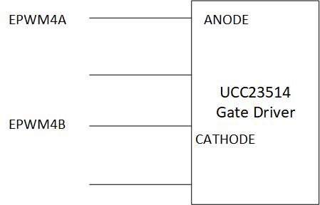
I am using 28379D T1/T2 event inside the EPWM action qualifier to regulate the sync buck inductor current. For testing, I am using a fixed 50% duty ratio. Part of ePWM is shown below. DCAEVT2 from CMPSS is linked to T2 event source. 

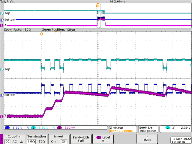
I record the test waveform. Light blue is the inductor voltage and Purple is the inductor current. I can see the current was able to regualted by the ePWM module, but there are some short pulses, which happened unexpected (close to the second cursor). Since I only make the EPWM output high when the counter equal to CMPA, the voltage pulse can only happen every 20 us, but that unexpected short pulse happens about 65us after the previous one. When ePWM counter is counting up, if T2 event becomes false (inductor current drops below threshold) after counter is greater than CMPA, will the EPWM still try to output high? It seems to me this is the only possibility to make this short pulse happen. Is there a way we can avoid this short pulse by keep using T1/T2 event?

I am looking foreard to your reply! 

   EPwm4Regs.CMPA.bit.CMPA = 250;  

   EPwm4Regs.TBPHS.all = 0; 

   EPwm4Regs.TBCTL.bit.PHSEN = TB_ENABLE;    //slave mode

    EPwm4Regs.TBCTL.bit.PRDLD = TB_SHADOW;

    EPwm4Regs.TBCTL.bit.SYNCOSEL = TB_SYNC_IN; //sync flow-through

    EPwm4Regs.TBPRD = 500;                // 500*2*0.02= 20 us for up and down

    EPwm4Regs.TBCTL.bit.CTRMODE = TB_COUNT_UPDOWN;

    EPwm4Regs.AQCTLA.bit.CAU = AQ_SET;

    EPwm4Regs.AQCTLA.bit.CAD = AQ_CLEAR;

    EPwm4Regs.AQCTLA2.bit.T2U = AQ_CLEAR;   // if over-current, upper switch output low

    EPwm4Regs.AQCTLA2.bit.T2D = AQ_CLEAR;   // if over-current, upper switch output low


    EPwm4Regs.DBCTL.bit.OUT_MODE = DB_FULL_ENABLE;       // Dead-band module

    EPwm4Regs.DBCTL.bit.POLSEL = DB_ACTV_HIC;            // Active High Compli

    EPwm4Regs.DBFED.all = 50;                            // 1 us deadtime

    EPwm4Regs.DBRED.all = 50;                            // 1 us deadtime


    EPwm4Regs.CMPCTL.bit.SHDWAMODE = CC_SHADOW;

    EPwm4Regs.CMPCTL.bit.SHDWBMODE = CC_SHADOW;

    EPwm4Regs.CMPCTL.bit.LOADAMODE = CC_CTR_ZERO;     //load on CTR = zero

    EPwm4Regs.CMPCTL.bit.LOADBMODE = CC_CTR_ZERO;     //load on CTR = zero


    EPwm4Regs.DCTRIPSEL.bit.DCAHCOMPSEL = 3;  // Take EPWM Trip 4 from Xbar

    EPwm4Regs.TZDCSEL.bit.DCAEVT2 = 2;        // DCAEVT2 happens when DCAH becomes high

    EPwm4Regs.DCACTL.bit.EVT2FRCSYNCSEL = 1;  // No sync needed

    EPwm4Regs.AQTSRCSEL.bit.T2SEL= 1;    // Select DCAEVT2 as T2 event source

  • Hi Kaiyu,

    Thank you for posting your question. I will go through this and provide a response by tomorrow.

    Best Regards,

    Marlyn

  • Hi Kaiyu,

    I have a few clarification questions for you:

     DCAEVT2 from CMPSS is linked to T2 event source.

    What is your CMPSS comparing? I see you mention the inductor current dropping below a threshold, is this what the comparator is checking?

    Light blue is the inductor voltage and Purple is the inductor current

    Can I please see your EPWM output as well?

    but that unexpected short pulse happens about 65us after the previous one

    How long is this short pulse in comparison to the prior pulses?

    Best Regards,

    Marlyn

  • Hi Marlyn,

    (1) CMPSS is taking the inductor current as the input, and compare to a fixed internal value, which is the threshold.

    (2) I will try to get it to you.

    (3) The short pulse only lasts for 1~2 us. The longer one is about 6~8 us.

    Kaiyu 

  • Hi Marlyn,

    I think I know the root cause now. I recorded the EPWM4A (Blue) and EPWM4B (Light Blue) when there is no over current in Fig 1.

    Because I configured it as active high complementary. It behaves as I expected.

    The strage thing happens when over-current occurs (Fig 2). Because CMPSS is taking the inductor current as the input, it will casue T2 event happen.

    EPWM4A is supposed to turned to LOW when T2 event occurs, but it doesn't.  EPWM4B is also not following the ative high complementary rule.

    Beaucse I connected EPWM4A and EPWM4B to gate dirver as Fig 3, the MOSFET only turns on when EPWM4A is high and EPWM4B is low.

    In this case, both EPWM4A and EPWM4B high will indirectly stops the MOSFET to turn ON, and inductor current will decrease. 

    I don't see any example about using T1/T2 event to run cycle-by-cycle current control. Can you review my code in my original post to provide the feedback?

    I cannot use trip zone because I have to use the dead band generator.


    Thanks,

    Kaiyu

    Fig 1  EPWM4A (Blue) and EPWM4B(Light Green) when no over-current  

    Fig 2  EPWM4A (Blue) and EPWM4B(Light Green) when over-current  

    Fig 3   Gate driver connection

  • Hi Kaiyu,

    Thank you for the further clarification on the issue and the output waveforms. 

    The code you have above looks okay from an EPWM perspective. Can I see your code for the comparator and your XBARs?

    Best Regards,

    Marlyn

  • Hi Marlyn,

    Here is the code. My concern is that the EPWM module seems not following the ative high complementary rule. It will make the half bridge shoot-through if I didn't put the hardware interlock.

    Kaiyu 

    EALLOW;

    //
    //Enable CMPSS
    //
    Cmpss3Regs.COMPCTL.bit.COMPDACE = 1;

    //
    //NEG signal comes from DAC
    //
    Cmpss3Regs.COMPCTL.bit.COMPHSOURCE = NEGIN_DAC; // use DAC value

    //
    //Use VDDA as the reference for DAC
    //
    Cmpss3Regs.COMPDACCTL.bit.SELREF = REFERENCE_VDDA;

    //
    //Set DAC to midpoint for arbitrary reference

    Cmpss3Regs.DACHVALS.bit.DACVAL = 2500; //about 10A -> 2500


    //
    // Configure CTRIPOUT path
    //
    //

    Cmpss3Regs.CTRIPHFILCLKCTL.bit.CLKPRESCALE = 39; // 200MHz/(39+1)= 5MHz
    Cmpss3Regs.CTRIPHFILCTL.bit.SAMPWIN = 9; // Monitor 10 samples
    Cmpss3Regs.CTRIPHFILCTL.bit.THRESH = 9; // All 10 are good


    //
    //Reset filter logic & start filtering
    //
    Cmpss3Regs.CTRIPHFILCTL.bit.FILINIT = 1;
    //
    // Configure CTRIPOUT path
    // Digital filter output feeds CTRIPH and CTRIPOUTH
    //
    Cmpss3Regs.COMPCTL.bit.CTRIPHSEL = CTRIP_FILTER;

    //
    //Configure TRIP4 to be CMPSS3 output
    //
    EPwmXbarRegs.TRIP4MUX0TO15CFG.bit.MUX4 = 0;
    //
    //Enable TRIP4 Mux for Output
    //
    EPwmXbarRegs.TRIP4MUXENABLE.bit.MUX4 = 1; // MUX4 is connected to CMPSS3_H output
    EDIS;

  • Hi Kaiyu,

    Your code for the comparator and xbar looks good. 

    T1 and T2 operate in the same way as CMPA/CMPB would. If the event is present then the action you specified through the action qualifier submodule will take place. However, the next time there is a match in the counter compare for CMPA the output signal would be driven high again. The condition is not latched for T1 and T2. If you want 4A to go low based on the comparator output then I would recommend using the trip zone submodule. You can configure TZA and TZB bits of the TZCTL register for independent action on EPWM4A and EPWM4B upon the cycle by cycle trip condition. 

    I cannot use trip zone because I have to use the dead band generator

    There is no dependency between the two modules. If you want to keep the active high complementary pair that the dead band module provides you can set TZA to low (4A) and TZB to high (4B) to maintain this relationship. 

    I would also recommend checking if the DCAEVT2 bit of the TZFLG register is getting set to verify that the trip signal is occurring.

    Best Regards,

    Marlyn

  • Hi Marlyn,

    (1) I checked the trip zone function with the scope. When TZA goes to low and TZB goes to high, they happen at the same time, and there is no delay between then. I already see a lot of previous posts discussing this.

    (2) If I configured EPWM module active high complementary, it should follow the rule, but now I see both EPWMA and EPWMB go to high. This will cause catastrophic failure if there is no hardware interlock!!!

    Kaiyu

  • Hi Kaiyu,

    If you would like the dead-time to also apply when the trip is detected then I see two options you could follow.

    1) Use the CSFA /CSFB bits of the AQCSFRC register. This is a latched condition, meaning it will keep the outputs in the state defined until there is no longer a software force. Since this is happening before the dead-band submodule the dead-time should still be applied

    2) Instead of modifying the TZA/TZB bits of the TZCTL register you could force the EPWM A/B outputs to a certain state directly from the digital compare outputs. The outputs will remain in that state until the condition of DCxEVT1/2 is cleared. How is this different from the previous suggestion? With this you have the ability to directly affect channel A or channel B output. You could utilize the event filtering block of the digital compare submodule to add some delay time between the DC event affecting EPWM A or B output.

    Best Regards,

    Marlyn

  • Thank you, Marlyn! I know there must be some other methods which could be used. It seems to me T1/T2 events cannot be used in this application for cycle-by-cycle current control. Coud you please confirm this? Is this the design imperfection for active high complementary when T1/T2 happens?

    Kaiyu 

  • Hi Kaiyu,

    It seems to me T1/T2 events cannot be used in this application for cycle-by-cycle current control. Coud you please confirm this?

    Yes, this is correct.

    Is this the design imperfection for active high complementary when T1/T2 happens?

    T1 and T2 are inputs into the action qualifier but other events also programmed with the action qualifier submodule will occur if the right conditions are met. I don't think this is a design imperfection, this is just how the design was intended for T1 and T2. 

    Best Regards,

    Marlyn

  • Hi Kaiyu,

    Are you still facing the issue with the dead-band module not following the active high complementary condition? If so, I can use your code to try to replicate this issue on my side. 

    Best Regards,

    Marlyn

  • Hi Marlyn,

    The dead-band module is not following the active high complementary if I am using T1/T2 event. It will be greatly appreciated if you could try to replicate the issue from your side.

    Thanks,

    Kaiyu

  • Hi Kaiyu,

    I was able to replicate this issue on my side as well. I have submitted a request to our design team to investigate this further but it may take some time. I will keep you updated on the status. 

    In the mean-time have you been able to look into any of the other suggested methods?

    Best Regards,

    Marlyn

  • Hi Marlyn,

    Thank you for taking effort to replicate the test! I am glad it is not my code bug causing this issue Slight smile 

    Yes. right now, I am using your trip zone feature combined with my hardware rising edge delay to accomplish my task.

    Best Regards,

    Kaiyu

  • Hi Kaiyu,

    Thank you for taking effort to replicate the test! I am glad it is not my code bug causing this issue

    Absolutely, I will keep you up to date with any changes as I receive further information. 

    Yes. right now, I am using your trip zone feature combined with my hardware rising edge delay to accomplish my task.

    Glad to hear! Please let me know if you run into any further issues or have questions in the process.

    Best Regards,

    Marlyn