This thread has been locked.

If you have a related question, please click the "Ask a related question" button in the top right corner. The newly created question will be automatically linked to this question.

TMS320F280025: Intermediate PWM transition issue.

Part Number: TMS320F280025
Other Parts Discussed in Thread: SYSCONFIG, C2000WARE

I opened a thread some time ago but could not resolve the issue at that time. We have configured some PWMs for 20 KHz frequency and centre aligned mode.  The setup code is given below:

// Set-up TBCLK
    //Device clock is 100 MHz
    EPWM_setTimeBasePeriod(base, 2500);
    EPWM_setPhaseShift(base, 0U);
    EPWM_setTimeBaseCounter(base, 0U);
    EPWM_setTimeBaseCounterMode(base, EPWM_COUNTER_MODE_UP_DOWN);
    EPWM_disablePhaseShiftLoad(base);

    //
    // Set ePWM clock pre-scaler
    //
    EPWM_setClockPrescaler(base, EPWM_CLOCK_DIVIDER_1, EPWM_HSCLOCK_DIVIDER_1);

    //
    // Set up shadowing
    //
    EPWM_setCounterCompareShadowLoadMode(base, EPWM_COUNTER_COMPARE_A,
                                         EPWM_COMP_LOAD_ON_CNTR_ZERO);

   
    //
    // Set actions
    //
    EPWM_setActionQualifierAction(base, EPWM_AQ_OUTPUT_A, EPWM_AQ_OUTPUT_LOW,
                                  EPWM_AQ_OUTPUT_ON_TIMEBASE_ZERO);
    EPWM_setActionQualifierAction(base, EPWM_AQ_OUTPUT_A, EPWM_AQ_OUTPUT_HIGH,
                                  EPWM_AQ_OUTPUT_ON_TIMEBASE_UP_CMPA);
    EPWM_setActionQualifierAction(base, EPWM_AQ_OUTPUT_A,
                                  EPWM_AQ_OUTPUT_NO_CHANGE,
                                  EPWM_AQ_OUTPUT_ON_TIMEBASE_PERIOD);
    EPWM_setActionQualifierAction(base, EPWM_AQ_OUTPUT_A, EPWM_AQ_OUTPUT_LOW,
                                  EPWM_AQ_OUTPUT_ON_TIMEBASE_DOWN_CMPA);

 
        EPWM_setActionQualifierAction(base, EPWM_AQ_OUTPUT_B,
                                      EPWM_AQ_OUTPUT_LOW,
                                      EPWM_AQ_OUTPUT_ON_TIMEBASE_ZERO);
        EPWM_setActionQualifierAction(base, EPWM_AQ_OUTPUT_B,
                                      EPWM_AQ_OUTPUT_HIGH,
                                      EPWM_AQ_OUTPUT_ON_TIMEBASE_UP_CMPB);
        EPWM_setActionQualifierAction(base, EPWM_AQ_OUTPUT_B,
                                      EPWM_AQ_OUTPUT_NO_CHANGE,
                                      EPWM_AQ_OUTPUT_ON_TIMEBASE_PERIOD);
        EPWM_setActionQualifierAction(base, EPWM_AQ_OUTPUT_B,
                                      EPWM_AQ_OUTPUT_LOW,
                                      EPWM_AQ_OUTPUT_ON_TIMEBASE_DOWN_CMPB);

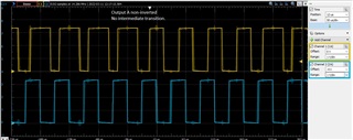
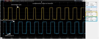
We had observed that there is an intermediate transition in duty cycle of the PWM whenever its duty cycle is changes.  Please refer to the image below:

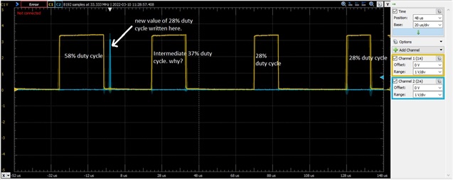
Initially the duty cycle is setup for 50%. Then at some instant shown by blue line the duty cycle us written for 28% We are using following function:

EPWM_setCounterCompareValue(base, EPWM_COUNTER_COMPARE_A,
duty_cycle_count);

However you can see that there is an intermediate period having duty cycle of 37%. We did the setting according to our understanding  that the new counter value will take effect from the start of the next PWM period.

EPWM_setCounterCompareShadowLoadMode(base, EPWM_COUNTER_COMPARE_A,
EPWM_COMP_LOAD_ON_CNTR_ZERO);

However we suspect that this is happening since the new counter value is taking effect in the middle of the period. How can we ensure that the duty cycle takes effect from the start of the period so that there is direct transition to our next intended duty cycle.

  • EPWM_setCounterCompareShadowLoadMode(base, EPWM_COUNTER_COMPARE_A,
    EPWM_COMP_LOAD_ON_CNTR_ZERO);

    You have this in your EPWM setting. Everything should work as you described.

    What are the two CMPA values you are using to get your Duty?

    Can you also run another EPWM in parallel that has the same period and TOGGLE at CTR=ZERO and CTR=PRD so we can see the CTR=ZRO and PRD events with respect to your updates?

  • Please find below the code snippet that is toggling between the two duty cycles. This code section is executing at 10 kHz so duty cycle change should happen every 1 mSec or after every 20 cycles. The blue line in my previous post shows gpio toggling point.  I will do the parallel pwm task tomorrow when I get back to office. Please let me know if additional information is needed. 

  • From what you have I dont see an issue yet. I would like to see where this is in the PWM cycle so I will await your parallel PWM implementation.

  • I want to add that the outputs A & B of the ePWM module are configured for complementary operation with dead band control. I have configured another PWM i.e. ePWM2 to transition at counter=0 (low to high) and counter = period events (high to low) as proposed by you. There is an interesting observation. The channel A has no intermediate transition whereas channel B (inverted) shows intermediate transition. I think this is the normal and correct behavior. It appears to be an overlook on our side that we were not looking at both the outputs. We were only looking at the inverted output that is acctually suppose to have one intermediate transition according to our complementary setup.

  • The addition of the EPWM is very helpful. In your scenario everything is based on A so it's good to see that is functional. Good work Asad!

    Have you checked out EPWM SysConfig?

    It's a GUI that generates your EPWM configuration for you.

    https://www.ti.com/lit/spracx3

    It's available in the new C2000Ware we release a couple days ago!

  • I will definitely explore epwn enhancement in sysconfig. Thanks for a prompt and very effective support.