


Part Number: TMS320F28388D
I have a problem when I'm using 28388 to do calculations for a PI controller. In my case, the PI controller is designed for a resonant converter. In the PI controller, the error signal is generated by comparing the output voltage of the converter with a fixed reference. (The output voltage is sensed and converted to digital through ADC.)
Below is my code for the PI calculation:
PI_err =PI_ref - PI_fdb; // calcuate Error by comparing the Reference and the Feedback output voltage
PI_out = PI_out + (Kp * PI_err + Ki * PI_err2); // PI outupt calculation (The PI_out determines the switching period of resonant converter, which is around 1700 in my case, and the actual switching period is 1700*5ns)
PI_err2 = PI_err; // "integration" of the error
where, Kp = 0.5, and Ki=-0.48
And the problem is: During the test, the closed-loop control is working well (My Reference is 120V, and the actual output voltage is regulated at 120+-0.3V). After converting these numbers by ADC, the Error (PI_err) is between -2 to 2, which means, the PI_out should change pretty smoothly. Let's take an extreme example, say PI_err = 2, and PI_err2 = -2; then PI_out = PI_out + (0.5*2 + (-0.48)*(-2)) = PI_out + 0.98. So the PI_out value should change only 1 at most from cycle to cycle. However, through the graphic tools, I can observe that there's often a spike in the PI_out (e.g. from 1703 to 1711 then back to 1704). Please see the picture below.
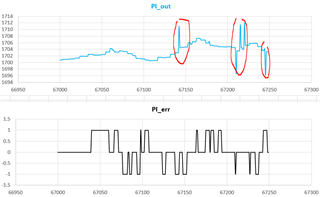
This spike will make the resonant converter kind of "unstable". But I don't understand how this spike comes. I don't think this should happen according to the calculations.
Can anyone help to explain or solve this issue? Many thanks!

