This thread has been locked.

If you have a related question, please click the "Ask a related question" button in the top right corner. The newly created question will be automatically linked to this question.

TMS320F28379D: Unexpected SCI Interrupt Causes Code To Freeze

Part Number: TMS320F28379D

I'm getting an unexpected SCI interrupt that causes the code to stop running. Here's the setup:

C2000 (TMS320F28379D) > SCI peripheral > externally connected to an RS-422 transceiver chip > switch

The purpose of the switch is to loopback the outputs of the transceiver chip to the inputs of the transceiver chip so we can easily run a serial loopback test with some dummy data using the C2000 SCI peripheral. Unfortunately, when we specifically switch from the loopback position to the open position (output/transmit is not looped back to input/receive) we observed via an oscilloscope that there are some voltage level changes, and if we switch it slow enough we see the serial input (rx) line go from high to low and then it stays low.

When the serial input line stays low we also observed the code gets "stuck" and when I connect a debugger and pause the execution it is in the SCI rx interrupt. Why would the SCI receive line being held low or transitioning from high to low cause the code to stop executing? Is it being faked out and it can't recover from this condition?

Thanks!

  • Hi Nigel,

    When the serial input line stays low we also observed the code gets "stuck" and when I connect a debugger and pause the execution it is in the SCI rx interrupt.

    Within the RX interrupt are you checking for any kind of errors (SCIRXST Register)? This can give us some indication of what is happening. If there is an error then the SCI module needs a software reset to clear the error conditions. Even within the interrupt is there any particular line that causes the code to hang? 

    Here is our SCI debug check-list that also contains information that might help: https://e2e.ti.com/support/microcontrollers/c2000-microcontrollers-group/c2000/f/c2000-microcontrollers-forum/1031947/faq-my-c2000-sci-is-not-transmitting-and-or-receiving-data-correctly-how-do-i-fix-this 

    Best Regards,

    Marlyn

  • Marlyn, here is the code, note that we are using nested interrupts:

    __attribute__((ramfunc))
    __interrupt static void scib_rx_isr(void)
    {
        // save IER register on stack
        volatile uint16_t tempPIEIER = PieCtrlRegs.PIEIER9.all;
        
        // set global & group priority to allow CPU interrupts with higher priority
        IER |= M_INT9;
        IER &= MINT9;
        PieCtrlRegs.PIEIER9.all &= MG9_3;
        
        // allow higher priority interrupts to come through
        PieCtrlRegs.PIEACK.all = 0xFFFFu;
        __asm(" NOP"); // to avoid spurious nested interrupts, see 4.1.1 in silicon errata (SPRZ412L rev. June 2020)
        EINT;
        
        uint32_t interruptStatus = SCI_getInterruptStatus(SCIB_BASE);
        const uint32_t interruptErrors = (SCI_INT_RXERR | SCI_INT_FE | SCI_INT_OE | SCI_INT_PE);
        
        if (interruptStatus & interruptErrors) // clear errors and skip interrupt
        {
            SCI_clearInterruptStatus(SCIB_BASE, interruptErrors);
        }
        else // no SCIB Rx errors, receive data
        {
            uint16_t byte = (uint16_t) ScibRegs.SCIRXBUF.bit.SAR; // Driverlib: SCI_readCharNonBlocking(SCIB_BASE);
        }
        
        // Reset buffer/interrupts
        ScibRegs.SCIFFRX.bit.RXFFOVRCLR = 1; // Driverlib: SCI_clearOverflowStatus(SCIB_BASE);
        ScibRegs.SCIFFRX.bit.RXFFINTCLR = 1; // Driverlib: SCI_clearInterruptStatus(SCIB_BASE, SCI_INT_RXFF);
        //PieCtrlRegs.PIEACK.bit.ACK9 = 1; // Driverlib: Interrupt_clearACKGroup(INTERRUPT_ACK_GROUP9);
        
        // disable interrupts & restore saved registers
        DINT;
        PieCtrlRegs.PIEIER9.all = tempPIEIER;
    }

    I'll have to double check with our electrical team regarding any pull-up resistors in the circuitry to pull the RX line to the IDLE HIGH state when nothing is driving. It's possible the test circuitry contained a short between the differential receive lines causing an "active" low event.

  • Hi Nigel,

    I do see that you have a condition for errors. Does your code ever enter the if statement? You could check this by putting a software breakpoint and seeing if the code ever reaches the line within the if statement.

    I'll have to double check with our electrical team regarding any pull-up resistors in the circuitry to pull the RX line to the IDLE HIGH state when nothing is driving. It's possible the test circuitry contained a short between the differential receive lines causing an "active" low event.

    Yes, please double check this.

    Best Regards,

    Marlyn

  • I was able to debug further...

    1) Yes, the code enters the if statement, it will sometimes return one status and then another, I've included the statuses I've observed as well as the defined SCI flags/errors for reference:

    status (bad) = 0x3D = 0011 1101 (SCI_INT_RXERR, SCI_INT_TXRDY, SCI_INT_TXFF, SCI_INT_RXFF, SCI_INT_FE)

    status (good) = 0x1C = 0001 1100 (SCI_INT_TXRDY, SCI_INT_TXFF, SCI_INT_RXFF)

    #define SCI_INT_RXERR          0x01U  //!< RXERR interrupt
    #define SCI_INT_RXRDY_BRKDT    0x02U  //!< RXRDY interrupt
    #define SCI_INT_TXRDY          0x04U  //!< TXRDY interrupt
    #define SCI_INT_TXFF           0x08U  //!< TX FIFO level interrupt
    #define SCI_INT_RXFF           0x10U  //!< RX FIFO level interrupt
    #define SCI_INT_FE             0x20U  //!< Frame Error
    #define SCI_INT_OE             0x40U  //!< Overrun Error
    #define SCI_INT_PE             0x80U  //!< Parity Error

    2) EE confirmed that we do not need a pull-up resistor as our RS-422 transceiver is always in an active/driven state (never high impedance/floating). Likely the test circuitry was pulling the RS422+ line low and pulling the RS422- line high, and because the RS422- line gets inverted and RS-422 is a differential signal the output is driven/held low. I was able to recreate this scenario with one of our logic analyzers by outputting a +5V DC signal on the RS422- line and get the same result where the code is stuck in the interrupt when the line is held low.

  • Hi Nigel,

    Likely the test circuitry was pulling the RS422+ line low and pulling the RS422- line high, and because the RS422- line gets inverted and RS-422 is a differential signal the output is driven/held low.

    The RX line must be held high between data bytes, else the SCI will trigger a "Start of Byte/Frame" in the logic and since it is continuously being held low without data this will cause SCI errors. I think this is why your rx interrupt looks like its "stuck". You are not clearing any errors and if the interrupt is setup to occur when data is received or there are errors then this interrupt will be always occurring as long as the sci rx line is being driven continuously low. 

    So, it appears the transceiver being used is not behaving properly. The RX pin on the C2000 device cannot drive itself, and so the reason for the RX being pulled low is external to the SCI module of C2000. This is something you would have to debug within your system.

    Best Regards,

    Marlyn

  • The RX line must be held high between data bytes, else the SCI will trigger a "Start of Byte/Frame" in the logic and since it is continuously being held low without data this will cause SCI errors.

    Can you clarify this statement? How does the SCI peripheral know when to trigger a "Start of Byte/Frame"? Is it when it encounters a HIGH to LOW transition or anytime the line is held LOW? Is there no way to handle the receive line being held continuously low?

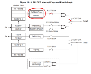
    Also, according to the TRM Figure 19-10. SCI FIFO Interrupt Flags and Enable Logic, with my current configuration the only possible way to trigger an RXINT interrupt, as far as I know, is if either the RXFFIL or RXFFOVF flag is set (i.e. something is in the receive FIFO or receive FIFO overflow). I enable RXFFIENA and SCIFFENA. I disable RXERRINTENA and RX/BKINTENA so no errors should trigger an interrupt, only if something is in the FIFO, which apparently it thinks there is? Clearly I'm missing something here.

    I think this is why your rx interrupt looks like its "stuck". You are not clearing any errors

    I am clearing errors? Anytime I receive an error I'm performing a SCI peripheral reset as you've mentioned before:

    If there is an error then the SCI module needs a software reset to clear the error conditions.

    I've updated my code to also include SCI_INT_RXRDY_BRKDT and I directly reset the SCI peripheral now if there are any errors which results in all the flags being cleared (both my old and new code reset the SCI peripheral so resetting the error flags is not the issue):


    __attribute__((ramfunc))
    __interrupt static void scib_rx_isr(void)
    {
        // save IER register on stack
        volatile uint16_t tempPIEIER = PieCtrlRegs.PIEIER9.all;
    
        // set global & group priority to allow CPU interrupts with higher priority
        IER |= M_INT9;
        IER &= MINT9;
        PieCtrlRegs.PIEIER9.all &= MG9_3;
    
        // allow higher priority interrupts to come through
        PieCtrlRegs.PIEACK.all = 0xFFFFu;
        __asm("  NOP"); // to avoid spurious nested interrupts, see 4.1.1 in silicon errata (SPRZ412L rev. June 2020)
        EINT;
    
        const uint32_t status = SCI_getInterruptStatus(SCIB_BASE);
        const uint32_t error_mask = (SCI_INT_RXERR | SCI_INT_RXRDY_BRKDT | SCI_INT_FE | SCI_INT_OE | SCI_INT_PE);
        const uint32_t errors = status & error_mask;
    
        if (errors != 0x0)
        {
            // Driverlib: SCI_performSoftwareReset(SCIB_BASE);
            ScibRegs.SCICTL1.bit.SWRESET = 0;
            ScibRegs.SCICTL1.bit.SWRESET = 1;
        
        else // no errors, parse received byte
        {
            static uint16_t idx = 0;
            uint16_t byte = (uint16_t) ScibRegs.SCIRXBUF.bit.SAR; // Driverlib: SCI_readCharNonBlocking(SCIB_BASE);
        }
    
        // reset buffer/interrupts
        ScibRegs.SCIFFRX.bit.RXFFOVRCLR = 1; // Driverlib: SCI_clearOverflowStatus(SCIB_BASE);
        ScibRegs.SCIFFRX.bit.RXFFINTCLR = 1; // Driverlib: SCI_clearInterruptStatus(SCIB_BASE, SCI_INT_RXFF);
    
        // disable interrupts & restore saved registers
        DINT;
        PieCtrlRegs.PIEIER9.all = tempPIEIER;
    }

    if the interrupt is setup to occur when data is received or there are errors then this interrupt will be always occurring as long as the sci rx line is being driven continuously low.

    As mentioned above, I should only get interrupted when I receive data in the FIFO, not when there are errors.

    So, it appears the transceiver being used is not behaving properly. The RX pin on the C2000 device cannot drive itself, and so the reason for the RX being pulled low is external to the SCI module of C2000. This is something you would have to debug within your system.

    To clarify, the transceiver is working fine, I am purposely driving the SCI receive line low externally. I realize this causes errors, but the code should be able to handle/recover errors without hanging up the rest of the processor or being "stuck" inside of an interrupt. This is what I'm trying to figure out is why it gets stuck endlessly in the interrupt and how to recover automatically.

    To help with further debugging I've included my SCI configuration as well:

    #define BAUD         4147200u   // 4.1472 Mbaud
    #define LSPCLK_FREQ  100000000u // 1MHz
    #define CONFIG       (SCI_CONFIG_WLEN_8 | SCI_CONFIG_PAR_NONE | SCI_CONFIG_STOP_ONE) // 8-N-1
    
    void initialize_sci(void)
    {
        // NOTE: GPIO configuration and peripheral clock/enable is done elsewhere
        Interrupt_register(INT_SCIB_RX, scib_rx_isr);
        SCI_setConfig(SCIB_BASE, LSPCLK_FREQ, BAUD, CONFIG);
        SCI_disableLoopback(SCIB_BASE);
        SCI_enableFIFO(SCIB_BASE);
        SCI_enableInterrupt(SCIB_BASE, SCI_INT_RXFF);
        SCI_disableInterrupt(SCIB_BASE, SCI_INT_RXERR);
        SCI_setFIFOInterruptLevel(SCIB_BASE, SCI_FIFO_TX1, SCI_FIFO_RX1);
        SCI_performSoftwareReset(SCIB_BASE);
        Interrupt_enable(INT_SCIB_RX);
        Interrupt_clearACKGroup(INTERRUPT_ACK_GROUP9);
    }

    Also I noticed something strange. This is likely my poor understanding of how the C2000 interrupt scheme works with nesting involved. I noticed when I enter the interrupt PieCtrlRegs.PIEIFR9.bit.INTx3 is set to 0 (shouldn't it be 1?), and when I set RXFFINTCLR to clear the RXFF interrupt status, immediately after this PieCtrlRegs.PIEIFR9.bit.INTx3 gets set to 1, which indicates to me that something is causing the interrupt to go pending again? Maybe this is why I'm stuck forever in the interrupt because it's always pending? I'm quite confused. Maybe it's just a coincidence that it occurs when I clear the RXFF interrupt status, but it's certainly not helping that the interrupt is pending again when the RXFF status is cleared. Maybe this is what is expected to happen because the line is held low and as soon as I clear the RXFF status the interrupt goes pending again? I could use further clarification on why the SCI receive interrupt goes pending again.

    Here's the really strange thing. When I insert a delay between clearing the overflow status bit and clearing the RXFF status, and then I perform a processor reset setting a breakpoint in the ISR, I hit the breakpoint 7 times (seven SCI B RX interrupts), but then I never receive an interrupt again (PieCtrlRegs.PIEIFR9.bit.INTx3 remains 0) and the code performs as normal. Did this somehow break the SCI B peripheral?

        ScibRegs.SCIFFRX.bit.RXFFOVRCLR = 1; // Driverlib: SCI_clearOverflowStatus(SCIB_BASE);
        // DELAY(100us);
        ScibRegs.SCIFFRX.bit.RXFFINTCLR = 1; // Driverlib: SCI_clearInterruptStatus(SCIB_BASE, SCI_INT_RXFF);

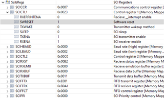
    Here's a screenshot of ScibRegs after the seven interrupts:

    I also have a question regarding the datasheet section 19.13.1 SCI FIFO Description:

    1. Reset. At reset the SCI powers up in standard SCI mode and the FIFO function is disabled. 

    Does this mean that when I get an error and reset the SCI peripheral all of my configurations are wiped? Could this be the cause of any issues I'm noticing? Should I be re-configuring the SCI peripheral to re-enable FIFO and all the other configurations I mentioned above?

  • Hi Nigel,

    Can you clarify this statement? How does the SCI peripheral know when to trigger a "Start of Byte/Frame"? Is it when it encounters a HIGH to LOW transition or anytime the line is held LOW? Is there no way to handle the receive line being held continuously low?

    The start of frame should be a recognized "low-bit". The SCI will then count the next set of bits as the data, parity, stop etc.

    I disable RXERRINTENA and RX/BKINTENA so no errors should trigger an interrupt, only if something is in the FIFO, which apparently it thinks there is? Clearly I'm missing something here.

    Would it be possible to toggle a gpio at the beginning of the ISR? I would like to see if this timing is consistent and it follows your baud rate to help indicate if the SCI module is "receiving data" that is all zeros.

    To clarify, the transceiver is working fine, I am purposely driving the SCI receive line low externally. I realize this causes errors, but the code should be able to handle/recover errors without hanging up the rest of the processor or being "stuck" inside of an interrupt. This is what I'm trying to figure out is why it gets stuck endlessly in the interrupt and how to recover automatically.

    I believe this is because the start bit of the frame is suppose to be a low bit. For SCI communication the line should be at a "high" state when not sending a frame (see here- https://www.avrfreaks.net/comment/441832#comment-441832 ). This way when the line does go low for a bit the SCI knows that is the beginning of the frame. Is it possible for you to try to run the code with the RX line being held "high" while idle? Note, this is not something TI specific, but rather industry recognized, it is part of the protocol. 

    Here's the really strange thing. When I insert a delay between clearing the overflow status bit and clearing the RXFF status, and then I perform a processor reset setting a breakpoint in the ISR, I hit the breakpoint 7 times (seven SCI B RX interrupts), but then I never receive an interrupt again (PieCtrlRegs.PIEIFR9.bit.INTx3 remains 0) and the code performs as normal. Did this somehow break the SCI B peripheral?

    Does the code perform "as normal" for the rest of the duration or does it eventually go back into the troubling state?

    Does this mean that when I get an error and reset the SCI peripheral all of my configurations are wiped? Could this be the cause of any issues I'm noticing? Should I be re-configuring the SCI peripheral to re-enable FIFO and all the other configurations I mentioned above?

    No, the configuration will remain as-in. Here is part of the description in the TRM for the SWRESET bit: "0h (R/W) = Initializes the SPI operating flags to the reset condition. Specifically, the RECEIVER OVERRUN Flag bit (SPISTS.7), the SPI INT FLAG bit (SPISTS.6), and the TXBUF FULL Flag bit (SPISTS.5) are cleared. SPISTE will become inactive. SPICLK will be immediately driven to 0 regardless of the clock polarity. The SPI configuration remains unchanged. "

    Best Regards,

    Marlyn

  • Would it be possible to toggle a gpio at the beginning of the ISR? I would like to see if this timing is consistent and it follows your baud rate to help indicate if the SCI module is "receiving data" that is all zeros.

    I set a spare GPIO HIGH at the beginning of the SCI receive interrupt and then set it LOW at the end of the interrupt. When the SCI receive line is held low I observe the interrupt continuing to happen periodically every 1.65us. The interrupt itself takes 260ns to execute.

    I believe this is because the start bit of the frame is suppose to be a low bit. For SCI communication the line should be at a "high" state when not sending a frame (see here- https://www.avrfreaks.net/comment/441832#comment-441832 ). This way when the line does go low for a bit the SCI knows that is the beginning of the frame. Is it possible for you to try to run the code with the RX line being held "high" while idle? Note, this is not something TI specific, but rather industry recognized, it is part of the protocol. 

    This is the whole point of this post. I already understand how SCI works in the ideal situation (RX line held "high" and then going "low", sending some data, then going back to idle "high"). The SCI transaction works just fine in the ideal situation. My question is how to recover from the SCI line being held "low" and remaining "low". This may happen at any time and is not ideal but I need a solution to this problem. Rather than completely blocking the processor by flooding it with SCI receive interrupts since the line is held "low", I need a solution that can detect this condition and recover, ignoring any further SCI communications until the line is pulled to the idle state again.

    Does the code perform "as normal" for the rest of the duration or does it eventually go back into the troubling state?

    When I insert the delay, I receive 7 interrupts, then the SCI peripheral stops working (I stop receiving interrupts), and the rest of the code works normally since it is no longer interrupted.

    No, the configuration will remain as-in. Here is part of the description in the TRM for the SWRESET bit: "0h (R/W) = Initializes the SPI operating flags to the reset condition. Specifically, the RECEIVER OVERRUN Flag bit (SPISTS.7), the SPI INT FLAG bit (SPISTS.6), and the TXBUF FULL Flag bit (SPISTS.5) are cleared. SPISTE will become inactive. SPICLK will be immediately driven to 0 regardless of the clock polarity. The SPI configuration remains unchanged. "

    This is a quote from the SPI peripheral section...I assume you meant to paste from the SCI peripheral section for SCICTL1 Register bit SWRESET? In which case either way it looks like the SCI configurations are untouched by a peripheral reset.

    SCI software reset (active low).
    Writing a 0 to this bit initializes the SCI state machines and operating
    flags (registers SCICTL2 and SCIRXST) to the reset condition. The
    SW RESET bit does not affect any of the configuration bits.
    All affected logic is held in the specified reset state until a 1 is written
    to SW RESET (the bit values following a reset are shown beneath
    each register diagram in this section). Thus, after a system reset, reenable
    the SCI by writing a 1 to this bit. Clear this bit after a receiver
    break detect (BRKDT flag, bit SCIRXST, bit 5).
    SW RESET affects the operating flags of the SCI, but it neither
    affects the configuration bits nor restores the reset values. Once SW
    RESET is asserted, the flags are frozen until the bit is deasserted.
    The affected flags are as follows:
    Value After SW SCI Flag Register Bit
    RESET
    1 TXRDY SCICTL2, bit 7
    1 TX EMPTY SCICTL2, bit 6
    0 RXWAKE SCIRXST, bit 1
    0 PE SCIRXST, bit 2
    0 OE SCIRXST, bit 3
    0 FE SCIRXST, bit 4
    0 BRKDT SCIRXST, bit 5
    0 RXRDY SCIRXST, bit 6
    0 RX ERROR SCIRXST, bit 7
    Reset type: SYSRSn
    0h (R/W) = Writing a 0 to this bit initializes the SCI state machines
    and operating flags (registers SCICTL2 and SCIRXST) to the reset
    condition.
    1h (R/W) = After a system reset, re-enable the SCI by writing a 1
    to this bit.

  • Hi Nigel,

    Rather than completely blocking the processor by flooding it with SCI receive interrupts since the line is held "low", I need a solution that can detect this condition and recover, ignoring any further SCI communications until the line is pulled to the idle state again.

    The SCI module is behaving as expected from a device point of view. As stated previously, the issue should be corrected to prevent the rx line from ever being continuously low not trying to resolve this within the C2000 device. The only proposed idea I can think of to help is the below. Note that this suggestion has not been tested or implemented by me.

    You could implement an external interrupt (XINT) from the rx input signal that is edge based, whenever the SCI rx line goes high. Within this external interrupt you can enable the RX interrupt and then disable the external interrupt itself. Then, within your RX interrupt you can continue to check for errors, primarily break detect errors. If one or more break detect errors occur back to back you know that the rx line is being held low. In this case you can re-enable the external interrupt (so that it may check when the rx line goes high again), and then disable the sci rx interrupt so that you don't get any further interrupts from the sci while the rx line is being held low.

    I assume you meant to paste from the SCI peripheral section for SCICTL1 Register bit SWRESET? In which case either way it looks like the SCI configurations are untouched by a peripheral reset.

    My apologies, yes, I meant SWREST bit of the SCICTL1 register. Correct, none of the actual configuration should change after performing a software reset.

    Best Regards,

    Marlyn

  • Thanks Marlyn, this ended up being the solution to recover from a SCI break condition. We ended up checking SCIRXST BRKDT == 1 to detect a break condition and turn off the interrupt. Then we have a task running in the background that monitors for the break condition to clear and re-enable the SCI interrupt, more specifically, if SCI break condition has been detected && SCI RX GPIO is IDLE HIGH 1 state then reset the SCI peripheral and re-enable the SCI rx interrupt.