


Part Number: TMS320F28379D
Hello everyone,
I am working with the SPI module on the F28379D board. On my master end, I currently have my character length set to 16 bits. However, I wish to change this to 8 bits. When I attempt to do this by setting the SPI character control bits to 8 as follows: SpiaRegs.SPICCR.bit.SPICHAR = 0x7, I stop getting any data written altogether on my MOSI line.
I've tested this by transmitting 0xAA and 0xAAAA, when the SPICHAR bits are set to 8 and 16 bits respectively. When they are set to 16 bits, I get the correct transmission show up on my oscilloscope. However, when they are set to 8 bits, I get nothing on my SDI line.
I wanted to figure out why this is happening and how I can fix it.
Below are my oscilloscope plots:
Scope when SPICHAR = 16 bits (data transmitted on SDI 0xAAAA)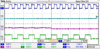
Scope when SPICHAR = 8 bits (data transmitted on SDI 0xAA)
Below is my code listing
// Included Files

#include "preprocessor.h"
#include "F28x_Project.h"
#include "spi_globals.h"
#include "spi_defines.h"
#include "function_defs.h"

void scan_test(void);


void main(void)
{
/*INITIALISATION----------------------*/

// SETUP CLOCK FREQUENCY


EALLOW;
// ClkCfgRegs.LOSPCP.bit.LSPCLKDIV = 0b100;
EDIS;

/* SETUP CODE */


// PRELIMINARY STEPS
InitSysCtrl(); // Step 1. Initialize System Control:

InitSpiaGpio(); // Step 2. Initialize GPIO:

DINT; // Step 3. Clear all interrupts:

InitPieCtrl(); // Initialize PIE control registers to their default state.


// Disable CPU __interrupts and clear all CPU __interrupt flags:
IER = 0x0000;
IFR = 0x0000;

// Initialize the PIE vector table with pointers to the shell Interrupt Service Routines (ISR).
InitPieVectTable();


// Step 4. Initialize the Device Peripherals:
spi_fifo_init(); // Initialize the Spi FIFO
spi_init(); // init SPI


/*COMMAND SECTION----------------------*/


// TRANSMIT ON SDI
// SpiaRegs.SPITXBUF = 0xAA;
SpiaRegs.SPITXBUF = 0xAAAA;

}
Below is my setup for the SPI registers (also note, I am not using FIFO enhancements):
void spi_init()
{
// BIT FIELD SETUP
//---------------------------------------------------------------------------------------------------------------------
    EALLOW;


    // SPI CONFIFURATION CONTROL REGISTER                           // Reset on, rising edge, 16-bit char bits
    SpiaRegs.SPICCR.bit.SPISWRESET      = 0;                        // BIT 7        // SPI Software Reset
    SpiaRegs.SPICCR.bit.CLKPOLARITY     = 0;                        // BIT 6        // Shift Clock Polarity
    SpiaRegs.SPICCR.bit.HS_MODE         = 0;                        // BIT 5        // High Speed Mode Enable Bits
    SpiaRegs.SPICCR.bit.SPILBK          = 0;                        // BIT 4        // SPI Loopback Mode Select
//    SpiaRegs.SPICCR.bit.SPICHAR         = 0xF;
    SpiaRegs.SPICCR.bit.SPICHAR         = 0x7;


    // BIT 0-3      // Character Length Control Bits


    // SPI OPERATION CONTROL REGISTER                               // Enable master mode, normal phase,
    // ------------------------------                               // enable talk, and SPI int disabled.
    SpiaRegs.SPICTL.bit.OVERRUNINTENA   = 0;                        // BIT 4        // Overrun Interrupt Enable
    SpiaRegs.SPICTL.bit.CLK_PHASE       = 1;                        // BIT 3        // SPI Clock Phase Select
    SpiaRegs.SPICTL.bit.MASTER_SLAVE    = 1;                        // BIT 2        // SPI Network Mode Control
    SpiaRegs.SPICTL.bit.TALK            = 1;                        // BIT 1        // Transmit Enable
    SpiaRegs.SPICTL.bit.SPIINTENA       = 0;                        // BIT 0        // SPI Interrupt Enable


    // SPI BAUD RATE REGISTER
    SpiaRegs.SPIBRR.bit.SPI_BIT_RATE = 29;


    // SPI CONFIFURATION CONTROL REGISTER                           // Relinquish SPI from Reset
    SpiaRegs.SPICCR.bit.SPISWRESET = 1;                             // BIT 7
//    SpiaRegs.SPICCR.bit.CLKPOLARITY = 0;                            // BIT 6
//    SpiaRegs.SPICCR.bit.HS_MODE = 0;                                // BIT 5
//    SpiaRegs.SPICCR.bit.SPILBK = 0;                                 // BIT 4
//    SpiaRegs.SPICCR.bit.SPICHAR = 15;                               // BIT 0-3


    // SPI PRIORITY CONTROL REGISTER
    SpiaRegs.SPIPRI.bit.FREE = 1;                           // Set so breakpoints don't disturb xmission
    EDIS;
}
