This thread has been locked.

If you have a related question, please click the "Ask a related question" button in the top right corner. The newly created question will be automatically linked to this question.

TMS320F28379D: Trip-zone setting for IGBT gate drivers

Part Number: TMS320F28379D

Hi community!

Could anybody please help me with the following issue?

I want to use an IGBT gate driver whose fault flag (signal) does not latch, i.e., it is automatically reset in the next PWM cycle (such as ACPL330j). What is the best setting for ePWM trip-zones that provides the fastest reaction for disabling PWM signals? Should I connect the Fault signal of the gate driver to a GPIO and then trip the ePWM through X-bar when a fault condition happens?

Regards

  • Hi Jake,

    Should I connect the Fault signal of the gate driver to a GPIO and then trip the ePWM through X-bar when a fault condition happens?

    Yes! This is the best method for implementing a trip using an external signal.

    Best Regards,

    Marlyn

  • Thanks for the reply!

    As I have understood from TRM, I have to use a one-shot trip on /TZ1, /TZ2, /TZ3. Is it correct?

    How about Digital compare events? Which one do you propose to be used in the mentioned application?

    Besides, in the TRM, the difference between a one-shot trip and a cycle-by-cycle trip is not clear. Could you please briefly explain that?


    Best regards.

  • Hi Jake,

    I have to use a one-shot trip on /TZ1, /TZ2, /TZ3. Is it correct?

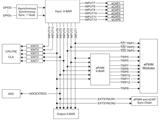
    Not necessarily. You can use the other trip signals as well, but you would have to configure the input XBAR and EPWMXBAR (see image below).

    TZ1, TZ2, and TZ3 are directly routed from the Input XBAR to the EPWM module and thus don't require the use of the EPWMXBAR.

    How about Digital compare events? Which one do you propose to be used in the mentioned application?

    This depends on how you are configuring the digital compare events. If you are using the CMPSS to compare your input against a certain threshold value then you have to use Trip4-Trip12 since the CMPSS signals are internally routed through the EPWMxBAR. If you still plan on only using a GPIO then you can use any of the trip inputs and setup the digital compare events based on that.

    Besides, in the TRM, the difference between a one-shot trip and a cycle-by-cycle trip is not clear. Could you please briefly explain that?

    Yes, I can explain a bit further, please let me know if this is still not clear.

    A cycle-by-cycle trip is used for current limiting operations. When a cycle-by-cycle trip is detected, the trip-zone submodule drives EPWMxA and EPWMxB to a certain specified state. The outputs will go back to their pre-trip state at the next ZRO, PRD, or ZRO/PRD events once the trip is no longer asserted.

    A one-shot trip is used for major short circuits or over-current conditions. When a one-shot trip is detected, the trip-zone submodule drives EPWMxA and EPWMxB to a certain specified state. The outputs will remain in that state until the trip is manually cleared through software.

    Best Regards,

    Marlyn

  • Thank you Marlyn for being so helpful.

    Regards.