This thread has been locked.

If you have a related question, please click the "Ask a related question" button in the top right corner. The newly created question will be automatically linked to this question.

TMS320F280049: XRSN Pin Glitch During Power Up

Part Number: TMS320F280049

Hi team,

My customer noticed the XRSN pin glitch issue.

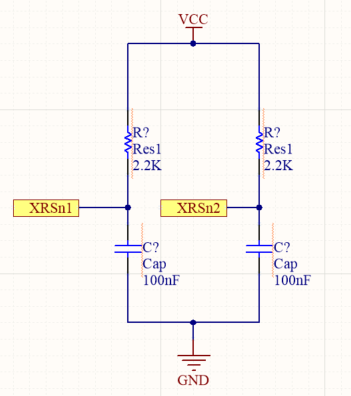
On this board, customer is using F280049+F280025 at the same time and XRSN glitch could be observed on both chips. Both XRSN is connected to 3.3V power rail with RC fitler (2.2k+100nF).


Questions:

1. What is the exact range of POR, the XRSN should be released 100ns after POR, but the exact POR point is not noted on the DS.

2. Why the XRSn are pulled down during power up? For me it seems the XRSN rise too soon before the 3.3V power up, thus there is something triggered and pulled the XRSn low;

3. On another board where only 1 F280025 is being used. We did not see the XRSN being pulled down.

Regards,

Brian

  • Hi Champs,

    Customer is looking for a confirmation and prepare for next PCB version. Your feedback would be appreciated. Thanks!

  • Hi Brian,

    On this board, customer is using F280049+F280025 at the same time and XRSN glitch could be observed on both chips. Both XRSN is connected to 3.3V power rail with RC fitler (2.2k+100nF).

    Can you provide the schematic portion of how both devices are connected to XRSn?

  • Hi Frank,

    Both XRSN pins are pulled high to 3.3V power rail with 2.2K resistor. The capacitor value is 100nF.

    Nothing special.

    Regards,

    Brian

  • Hi Brian,

    Thanks for providing the schematic. Responses to your questions below:

    1. What is the exact range of POR, the XRSN should be released 100ns after POR, but the exact POR point is not noted on the DS.

    100us not 100ns. The nominal I/O POR trip point is around 2.3v but it's a little more complicated than that. If you are interested, we added a dedicated PMM section in the F28003x datasheet (http://www.ti.com/lit/SPRSP61) page 75 onwards. It is very similar to the PMM in F28004x without the DCDC. We will be adding a similar PMM section to the F28004x device in the future.

    2. Why the XRSn are pulled down during power up? For me it seems the XRSN rise too soon before the 3.3V power up, thus there is something triggered and pulled the XRSn low;

    This is because the I/O BOR has different transition points during power up and power down. If VDDIO supply ramp is too slow, you will experience what you are seeing. There is no detriment to the device but if you are concerned, you can ramp the supply faster. We actually already have an errata on this behavior -> "BOR: VDDIO Between 2.45 V and 3.0 V can Result in Multiple XRSn Pulses"

  • Hi Frank,

    Thanks for the clarification, and we are indeed giving a lot more details in F28003x DS.

    For questions 2, I would suggest customer to check other PINs connected with XRSn. If no other PINs are influenced by the pulses, I would suggest them to ignore that.

    Regards,

    Brian

  • Hi Brian,

    For questions 2, I would suggest customer to check other PINs connected with XRSn. If no other PINs are influenced by the pulses, I would suggest them to ignore that.

    Correct. If XRSn signal from F280049 and F28002x isn't gating other devices, then they can safely ignore the toggles.