This thread has been locked.

If you have a related question, please click the "Ask a related question" button in the top right corner. The newly created question will be automatically linked to this question.

TMS320F28379D: Motor Control using TMS320F28379D

Part Number: TMS320F28379D
Other Parts Discussed in Thread: C2000WARE-MOTORCONTROL-SDK, C2000WARE, TMS320F280025, DRV8323, LAUNCHXL-F280025C, BOOSTXL-DRV8323RS

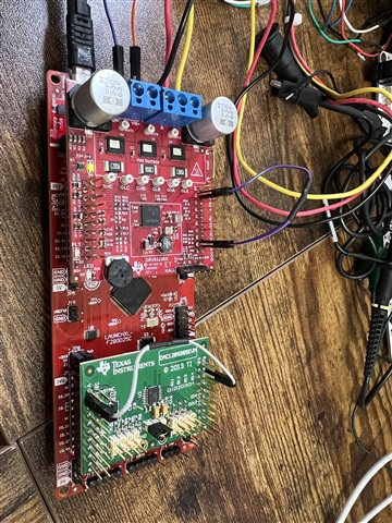
I am using TMS320F28379D for a BLDC Motor Control application. I am using DRV832RX as a driver and power stage. Is there any TI sdk example code that closely matches my application. 

  • RV832RX

    Seems like this part name is not right. There is not an example for TMS320F28379D with DRV8323RS. You can find an example withTMS320F280025 and DRV8323RS.

    You may download and install the latest MotorControlSDK. There is a new Universal Motor Control Lab that includes F28002x based BLDC Motor Control you want. The detailed introduction about the lab can be found in the lab user’s guide as the link below. You may follow the guide to port the lab to the TMS320F28379D you used.

    C2000WARE-MOTORCONTROL-SDK: https://www.ti.com/tool/C2000WARE-MOTORCONTROL-SDK

    Universal Project and Lab User’s Guide: https://www.ti.com/lit/spruj26

    Example lab project at the folder: C:\ti\c2000\C2000Ware_MotorControl_SDK_<version>\solutions\universal_motorcontrol_lab\f28002x

  • Hi Yanming,

    I am evaluating TMS320F280025 with DRV8323RS,  per the  Universal Motor Control Lab user guide. After finishing the hardware set up, as per the user guide , I am doing a level 1 build but my variable values don't match the description of the user guide(Fig 2-25 ) when I run the code. The motor voltage is being sensed correctly but the variable 'motorVars_M1.ISRCoun' is not increasing and I can not start the motor by setting 'motorVars_M1.flagEnableRunAndIdentify' to 1.


  • The GPIO29 must be connected to the DRV8323 enable pin on LAUNCHXL-F280025C. So you need to set the S2 on LAUNCHXL-F280025C to (1:1) position, GPIO28&GPIO29 need to be routed to the BP header by setting SEL1 of S2 to 1 (Close to the USB emulator).

    Or you may take a look at the links below that has similar question.

    https://e2e.ti.com/support/microcontrollers/c2000-microcontrollers-group/c2000/f/c2000-microcontrollers-forum/1061562/launchxl-f280025c-universal-motor-control-lab-incremental-build-1-with-boostxl-drv8323rs-and-sensored-foc/3933543#3933543

  • I have changed S2 position on LAUNCHXL-F280025C to (1:1 ). Afterwards, as you had mentioned in this ticket that the user need to modify the code for ISR count to increment. 

    "....The below code is removed in the release code. You can add it in the motor1CtrlISR() in motor1_drive.c file if you want.

    motorVars_M1.ISRCount++;

    "

    I modified this code to increment the ISR. Now, the counter is incrementing but the motor is still not spinning. The offset_V_sf for watching first element of the array [0] t is far off from the 0.5 value in the lab manual. Additionally, I noticed that the expression for the ePWM is different than the lab suggests(1666 Vs 1250). 


    Thanks,

    Jagbir

  • 1. Don't need to connect the motor in Build level 1, and the motor doesn't run in this level,

    2. The voltage offset value is still not correct, follow the lab guide to check the connection between the boostxl and launchxl by running the lab with build level 1.

  • Hi Yanming,

    I am trying to observe the output of the level1 build on an external oscilloscope . I am probing Pin(1,3 ** 11) of J4 on DRV8323RS evalkit but I am unable to visualize any PWM waveform on any of these pins. Is the PWM not being generated or I am probing the wrong pins.

    Feedback:

    The lab guide has a glaring number of omissions and corrections. The whole experience with this lab documentation has been really frustrating so far.

  • Thanks for your feedback. The lab guide is revising according to the feedback from our customers and FAEs, and it will be updated soon.

    I seems like the only missing content for DRV8323RS with Launchxl-f280025C could be that the switch S2 setting on Launchxl-f280025C.

    Yes. The PWM signals with 50% duty should be probed on the PINs (1/3/4/5/6/11). 

    Please connect a DC power supply (12V~40V) to DRV8323RS inverter board, and follow the guide to install the DRV8323RS to Launchxl-f280025C, and please make sure the booster-DRV8323RS is embedded on the right side (J1/J3 and J2/J4, close to the USB connector) of Launchxl-f280025C with the correct direction.

    On BOOSTXL-DRV8323RS:

    • Make sure that the following items are completed as described below, and then connect the BOOSTXL-DRV8323RS to J1/J3 and J4/J2 of the LAUNCHXL-F280025C.
      • Populate C9, C10, and C11 with a 47nF capacitor.
      • Bend J3-29 and J3-30 of the LAUNCHXL-F280025C90 degrees so that they are not connected to the BOOSTXL-DRV8323RS.

    On LAUNCHXL-F280025C:

    • Make sure that the switches on the LAUNCHXL-F280025C are set as described below
      • For S2, position the left switch up (1) to route GPIOs 28 and 29 to the BoosterPack connector, and position the right switch up (1) to rout GPIOs 16 and 17 to the virtual COM port.
      • For S3, position the left switch down to pull GPIO24 down to logic 0, and position the right switch up to pull GPIO32 up to logic 1 to put the F280025C into wait boot mode for reducing the risk of connectivity issues or a previous loaded code execution.
      • For S5, position the left switch down to route Q1 to J12 for the encoder interface on J12, and position the right switch down to route Q2 to J13 for the Hall sensor interface on J13.

    In lab project:

    • Make sure that the macro symbol "MOTOR1_FAST"  is defined in the project properties.
    • Set "motorVars_M1.flagEnableRunAndIdentify" to 1 to run the lab
    • Check if the "motorVars_M1.faultMtrUse.all" is equal to "0", if not, what value or bit is set in this variable.
  • Hi Yanming, 

    Thanks for your reply. I am able to run the lab up to level2, and spin the motor. Why am I observing different current and voltage offset for one of the array element. What are the consequences of a different offset on one of the phases. Do I need to remove this offset before I can move to level 3 and Level 4 builds.

  • Jagbir,

    Wanted to let you know that tommorow is US holiday for TI.  Please expect our next response by end of day on Monday.

    Best,

    Matthew

  • Please check ADC configuration if the right ADC channels are set for the voltage sensing and the capacitor is populated on booster inverter board. The offset calibration should be the similar value as shown in the lab.

    These offsets must be correct if you want to run the lab with FAST algorithm, otherwise, you can't run the motor with Level 4.

  • Hi,

    I want to use a different BLDC motor. Which files in the lab exercise need to be modified to use a different motor.

  • To set/change  the right motor parameters in "user_mtr1.h" according to the motor datasheet. Not all of the parameters are needed, follow the lab's guide to change the related parameters.

    #define USER_MOTOR1_TYPE MOTOR_TYPE_PM
    #define USER_MOTOR1_NUM_POLE_PAIRS (4)
    #define USER_MOTOR1_Rr_Ohm (NULL)
    #define USER_MOTOR1_Rs_Ohm (0.452883422f)
    #define USER_MOTOR1_Ls_d_H (0.000148176361f)
    #define USER_MOTOR1_Ls_q_H (0.000148176361f)
    #define USER_MOTOR1_RATED_FLUX_VpHz (0.0401013345f)
    #define USER_MOTOR1_MAGNETIZING_CURRENT_A (NULL)
    #define USER_MOTOR1_RES_EST_CURRENT_A (1.5f)
    #define USER_MOTOR1_IND_EST_CURRENT_A (-1.0f)
    #define USER_MOTOR1_MAX_CURRENT_A (6.0f)
    #define USER_MOTOR1_FLUX_EXC_FREQ_Hz (40.0f)
    #define USER_MOTOR1_NUM_ENC_SLOTS (1000)
    #define USER_MOTOR1_INERTIA_Kgm2 (7.06154e-06)

    #define USER_MOTOR1_FREQ_NEARZEROLIMIT_Hz (5.0f) // Hz

    #define USER_MOTOR1_RATED_VOLTAGE_V (24.0f)
    #define USER_MOTOR1_RATED_SPEED_KRPM (3.0f)

    #define USER_MOTOR1_FREQ_MIN_Hz (9.0f) // Hz
    #define USER_MOTOR1_FREQ_MAX_Hz (600.0f) // Hz

    #define USER_MOTOR1_FREQ_LOW_Hz (5.0f) // Hz
    #define USER_MOTOR1_FREQ_HIGH_Hz (300.0f) // Hz
    #define USER_MOTOR1_VOLT_MIN_V (5.0f) // Volt
    #define USER_MOTOR1_VOLT_MAX_V (24.0f) // Volt

    #define USER_MOTOR1_FORCE_DELTA_A (0.05f) // A
    #define USER_MOTOR1_ALIGN_DELTA_A (0.01f) // A
    #define USER_MOTOR1_FLUX_CURRENT_A (0.5f) // A
    #define USER_MOTOR1_ALIGN_CURRENT_A (1.0f) // A
    #define USER_MOTOR1_STARTUP_CURRENT_A (3.0f) // A
    #define USER_MOTOR1_TORQUE_CURRENT_A (2.0f) // A
    #define USER_MOTOR1_OVER_CURRENT_A (6.5f) // A

    #define USER_MOTOR1_BRAKE_CURRENT_A (1.0f) // A
    #define USER_MOTOR1_BRAKE_TIME_DELAY (12000U) // 60s/5ms

    #define USER_MOTOR1_SPEED_START_Hz (30.0f)
    #define USER_MOTOR1_SPEED_FORCE_Hz (25.0f)
    #define USER_MOTOR1_ACCEL_START_Hzps (10.0f)
    #define USER_MOTOR1_ACCEL_MAX_Hzps (50.0f)

    #define USER_MOTOR1_SPEED_FS_Hz (3.0f)

    // only for encoder
    #define USER_MOTOR1_ENC_POS_MAX (USER_MOTOR1_NUM_ENC_SLOTS * 4 - 1)
    #define USER_MOTOR1_ENC_POS_OFFSET (668)

    // Only for eSMO
    #define USER_MOTOR1_KSLIDE_MAX (0.75f) //
    #define USER_MOTOR1_KSLIDE_MIN (0.15f)

    #define USER_MOTOR1_PLL_KP_MAX (6.75f) //
    #define USER_MOTOR1_PLL_KP_MIN (0.75f)
    #define USER_MOTOR1_PLL_KP_SF (5.0f)

    #define USER_MOTOR1_BEMF_THRESHOLD (0.5f)
    #define USER_MOTOR1_BEMF_KSLF_FC_Hz (1.0f)
    #define USER_MOTOR1_THETA_OFFSET_SF (1.0f)
    #define USER_MOTOR1_SPEED_LPF_FC_Hz (200.0f)

    // for IS-BLDC
    #define USER_MOTOR1_RAMP_START_Hz (3.0f)
    #define USER_MOTOR1_RAMP_END_Hz (30.0f)
    #define USER_MOTOR1_RAMP_DELAY (5)

    #define USER_MOTOR1_ISBLDC_INT_MAX (0.015f)
    #define USER_MOTOR1_ISBLDC_INT_MIN (0.010f)

    // for Rs online calibration
    #define USER_MOTOR1_RSONLINE_WAIT_TIME (60000U) // 5min/300s at 5ms base
    #define USER_MOTOR1_RSONLINE_WORK_TIME (24000U) //2min/120s at 5ms base

  • HI Yanming,

    I am using my own motor to run build level 2. I have modified the "user_mtr1.h" according to the motor datasheet.  I am getting following errors flags. Any insight would be helpful.

    Thanks.

  • Which control algorithm are you using? You must set the correct motor parameter if you want to get the right feedback speed.

    Don't need to care the setting value in motorVars_M1.faultMtrPrev if the motorVars_M1.faultMtrUse.all equals to 0.

  • I believe I have entered the my motor parameters correctly. I am using FAST algorithm ,with V/F,I/F control as per level2 build of the lab . 

  • As mentioned above, check if ADC is configured correctly with the right channels for current and voltage sensing. Seems like it was not configured correctly in your project. The voltage offset is not correct, so the phase voltage feedback signals are not correct to estimate the speed and angle of the motor.

  • //#############################################################################
    // $TI Release: MotorControl SDK v4.00.00.00 $
    // $Release Date: Thu Feb 17 18:05:20 CST 2022 $
    // $Copyright:
    // Copyright (C) 2017-2019 Texas Instruments Incorporated - http://www.ti.com/
    //
    // Redistribution and use in source and binary forms, with or without
    // modification, are permitted provided that the following conditions
    // are met:
    //
    //   Redistributions of source code must retain the above copyright
    //   notice, this list of conditions and the following disclaimer.
    //
    //   Redistributions in binary form must reproduce the above copyright
    //   notice, this list of conditions and the following disclaimer in the
    //   documentation and/or other materials provided with the
    //   distribution.
    //
    //   Neither the name of Texas Instruments Incorporated nor the names of
    //   its contributors may be used to endorse or promote products derived
    //   from this software without specific prior written permission.
    //
    // THIS SOFTWARE IS PROVIDED BY THE COPYRIGHT HOLDERS AND CONTRIBUTORS
    // "AS IS" AND ANY EXPRESS OR IMPLIED WARRANTIES, INCLUDING, BUT NOT
    // LIMITED TO, THE IMPLIED WARRANTIES OF MERCHANTABILITY AND FITNESS FOR
    // A PARTICULAR PURPOSE ARE DISCLAIMED. IN NO EVENT SHALL THE COPYRIGHT
    // OWNER OR CONTRIBUTORS BE LIABLE FOR ANY DIRECT, INDIRECT, INCIDENTAL,
    // SPECIAL, EXEMPLARY, OR CONSEQUENTIAL DAMAGES (INCLUDING, BUT NOT
    // LIMITED TO, PROCUREMENT OF SUBSTITUTE GOODS OR SERVICES; LOSS OF USE,
    // DATA, OR PROFITS; OR BUSINESS INTERRUPTION) HOWEVER CAUSED AND ON ANY
    // THEORY OF LIABILITY, WHETHER IN CONTRACT, STRICT LIABILITY, OR TORT
    // (INCLUDING NEGLIGENCE OR OTHERWISE) ARISING IN ANY WAY OUT OF THE USE
    // OF THIS SOFTWARE, EVEN IF ADVISED OF THE POSSIBILITY OF SUCH DAMAGE.
    // $
    //#############################################################################
    
    #define USER_MTR1_H
    
    //
    //! \file   /solutions/universal_motorcontrol_lab/common/include/user_mtr1.h
    //! \brief  Contains the user related definitions
    //!
    //
    
    //*****************************************************************************
    //
    // If building with a C++ compiler, make all of the definitions in this header
    // have a C binding.
    //
    //*****************************************************************************
    #ifdef __cplusplus
    extern "C"
    {
    #endif
    
    //*****************************************************************************
    //
    //! \defgroup USER USER
    //! @{
    //
    //*****************************************************************************
    
    //
    // the includes
    
    // modules
    #include "userParams.h"
    
    #include "user_common.h"
    
    
    // *****************************************************************************
    // the defines
    
    //------------------------------------------------------------------------------
    
    //#define BSXL8323RS_REVA
    //! \brief Defines the nominal DC bus voltage, V
    //!
    #define USER_M1_NOMINAL_DC_BUS_VOLTAGE_V         (48.0f)
    
    //! \brief Defines the maximum voltage at the AD converter
    #define USER_M1_ADC_FULL_SCALE_VOLTAGE_V         (57.52845691f)
    
    //! \brief Defines the analog voltage filter pole location, Hz
    #define USER_M1_VOLTAGE_FILTER_POLE_Hz           (680.4839141f)     // 47nF
    
    //! \brief Defines the maximum current at the AD converter
    #define USER_M1_ADC_FULL_SCALE_CURRENT_A         (47.14285714f)     // gain=10
    
    //! \brief ADC current offsets for dc-link
    // the dc-link offset current for BSXL8323RS_REVA
    #define USER_M1_IDC_OFFSET_A            (USER_M1_ADC_FULL_SCALE_CURRENT_A / 2.0f)
    
    //! \brief ADC current offsets for A, B, and C phases
    #define USER_M1_IDC_OFFSET_AD           (2048.0f)
    
    #define USER_M1_IDC_OFFSET_AD_MAX       (USER_M1_IDC_OFFSET_AD + 100.0f)
    #define USER_M1_IDC_OFFSET_AD_MIN       (USER_M1_IDC_OFFSET_AD - 100.0f)
    
    //! \brief ADC current offsets for A, B, and C phases
    #define USER_M1_IA_OFFSET_AD    (2030.99646f)
    #define USER_M1_IB_OFFSET_AD    (2016.76001f)
    #define USER_M1_IC_OFFSET_AD    (2007.99329f)
    
    //! \brief ADC voltage offsets for A, B, and C phases
    #define USER_M1_VA_OFFSET_SF    (0.498977453f)
    #define USER_M1_VB_OFFSET_SF    (0.497419506f)
    #define USER_M1_VC_OFFSET_SF    (0.500700474f)
    
    //! \brief DC bus over voltage threshold
    #define USER_M1_OVER_VOLTAGE_FAULT_V        (54.5f)
    
    //! \brief DC bus over voltage threshold
    #define USER_M1_OVER_VOLTAGE_NORM_V         (52.5f)
    
    //! \brief DC bus under voltage threshold
    #define USER_M1_UNDER_VOLTAGE_FAULT_V       (8.0f)
    
    //! \brief DC bus under voltage threshold
    #define USER_M1_UNDER_VOLTAGE_NORM_V        (10.0f)
    
    //! \brief motor lost phase current threshold
    #define USER_M1_LOST_PHASE_CURRENT_A        (0.2f)
    
    //! \brief motor unbalance ratio percent threshold
    #define USER_M1_UNBALANCE_RATIO             (0.2f)
    
    //! \brief motor over load power threshold
    #define USER_M1_OVER_LOAD_POWER_W           (50.0f)
    
    //! \brief motor stall current threshold
    #define USER_M1_STALL_CURRENT_A             (90.8f)
    
    //! \brief motor fault check current threshold
    #define USER_M1_FAULT_CHECK_CURRENT_A       (0.4f)
    
    //! \brief motor failed maximum speed threshold
    #define USER_M1_FAIL_SPEED_MAX_HZ           (1500.0f)
    
    //! \brief motor failed minimum speed threshold
    #define USER_M1_FAIL_SPEED_MIN_HZ           (5.0f)
    
    //! \brief Defines the number of failed torque
    //!
    #define USER_M1_TORQUE_FAILED_SET           (0.000001f)
    
    // end of BSXL8323RS_REVA
    
    //------------------------------------------------------------------------------
    //! \brief ADC current offsets checking value for A, B, and C phases
    #define USER_M1_IA_OFFSET_AD_MAX    (USER_M1_IA_OFFSET_AD + 150.0f)
    #define USER_M1_IB_OFFSET_AD_MAX    (USER_M1_IB_OFFSET_AD + 150.0f)
    #define USER_M1_IC_OFFSET_AD_MAX    (USER_M1_IC_OFFSET_AD + 150.0f)
    
    #define USER_M1_IA_OFFSET_AD_MIN    (USER_M1_IA_OFFSET_AD - 150.0f)
    #define USER_M1_IB_OFFSET_AD_MIN    (USER_M1_IB_OFFSET_AD - 150.0f)
    #define USER_M1_IC_OFFSET_AD_MIN    (USER_M1_IC_OFFSET_AD - 150.0f)
    
    //! \brief ADC voltage offsets for A, B, and C phases
    #define USER_M1_VA_OFFSET_SF_MAX    (USER_M1_VA_OFFSET_SF + 0.05f)
    #define USER_M1_VB_OFFSET_SF_MAX    (USER_M1_VB_OFFSET_SF + 0.05f)
    #define USER_M1_VC_OFFSET_SF_MAX    (USER_M1_VC_OFFSET_SF + 0.05f)
    
    #define USER_M1_VA_OFFSET_SF_MIN    (USER_M1_VA_OFFSET_SF - 0.05f)
    #define USER_M1_VB_OFFSET_SF_MIN    (USER_M1_VB_OFFSET_SF - 0.05f)
    #define USER_M1_VC_OFFSET_SF_MIN    (USER_M1_VC_OFFSET_SF - 0.05f)
    
    //******************************************************************************
    //------------------------------------------------------------------------------
    //! \brief Vbus used to calculate the voltage offsets A, B, and C
    // =0.5*USER_M1_NOMINAL_DC_BUS_VOLTAGE_V
    #define USER_M1_VBUS_OFFSET_V  (0.5*USER_M1_ADC_FULL_SCALE_VOLTAGE_V)
    
    
    //! \brief Defines the maximum negative current to be applied in Id reference
    //!
    #define USER_M1_MAX_NEGATIVE_ID_REF_CURRENT_A       ((float32_t)(-2.0))
    
    
    //! \brief Defines the number of pwm clock ticks per isr clock tick
    //!        Note: Valid values are 1, 2 or 3 only
    #define USER_M1_NUM_PWM_TICKS_PER_ISR_TICK          (1)
    
    
    //! \brief Defines the number of ISR clock ticks per current controller clock tick
    //!
    #define USER_M1_NUM_ISR_TICKS_PER_CURRENT_TICK      (1)
    
    
    //! \brief Defines the number of ISR clock ticks per speed controller clock tick
    //!
    #define USER_M1_NUM_ISR_TICKS_PER_SPEED_TICK        (10)
    
    
    //! \brief Defines the number of current sensors
    //!
    #define USER_M1_NUM_CURRENT_SENSORS                 (3)
    
    
    //! \brief Defines the number of voltage sensors
    //!
    #define USER_M1_NUM_VOLTAGE_SENSORS                 (3)
    
    
    //! \brief Defines the Pulse Width Modulation (PWM) frequency, kHz
    //!
    #define USER_M1_PWM_FREQ_kHz        ((float32_t)(15.0f))
    #define USER_M1_PWM_TBPRD_NUM       (uint16_t)(USER_SYSTEM_FREQ_MHz * 1000.0f / USER_M1_PWM_FREQ_kHz / 2.0f)
    
    //! \brief Defines the Pulse Width Modulation (PWM) period, usec
    //!
    #define USER_M1_PWM_PERIOD_usec     ((float32_t)1000.0/USER_M1_PWM_FREQ_kHz)
    
    
    //! \brief Defines the Interrupt Service Routine (ISR) frequency, Hz
    //!
    #define USER_M1_ISR_FREQ_Hz         (USER_M1_PWM_FREQ_kHz * (float32_t)1000.0 / (float32_t)USER_M1_NUM_PWM_TICKS_PER_ISR_TICK)
    
    //! \brief Defines the SFRA sampling, Hz
    //!
    #define MOTOR1_SAMPLING_FREQ_HZ     USER_M1_ISR_FREQ_Hz
    
    
    //! \brief Defines the Interrupt Service Routine (ISR) period, usec
    //!
    #define USER_M1_ISR_PERIOD_usec     (USER_M1_PWM_PERIOD_usec * (float32_t)USER_M1_NUM_PWM_TICKS_PER_ISR_TICK)
    
    
    //! \brief Defines the direct voltage (Vd) scale factor
    //!
    #define USER_M1_VD_SF               ((float32_t)(0.95f))
    
    
    //! \brief Defines the voltage scale factor for the system
    //!
    #define USER_M1_VOLTAGE_SF          (USER_M1_ADC_FULL_SCALE_VOLTAGE_V / 4096.0f)
    
    //! \brief Defines the current scale factor for the system
    //!
    #define USER_M1_CURRENT_SF          (USER_M1_ADC_FULL_SCALE_CURRENT_A / 4096.0f)
    
    
    //! \brief Defines the current scale invert factor for the system
    //!
    #define USER_M1_CURRENT_INV_SF      (4096.0f / USER_M1_ADC_FULL_SCALE_CURRENT_A)
    
    
    //! \brief Defines the analog voltage filter pole location, rad/s
    //!
    #define USER_M1_VOLTAGE_FILTER_POLE_rps  (MATH_TWO_PI * USER_M1_VOLTAGE_FILTER_POLE_Hz)
    
    //! \brief Defines the maximum Vs magnitude in per units allowed
    //! \brief This value sets the maximum magnitude for the output of the Id and
    //! \brief Iq PI current controllers. The Id and Iq current controller outputs
    //! \brief are Vd and Vq. The relationship between Vs, Vd, and Vq is:
    //! \brief Vs = sqrt(Vd^2 + Vq^2).  In this FOC controller, the Vd value is set
    //! \brief equal to USER_MAX_VS_MAG*USER_VD_MAG_FACTOR.
    //! \brief so the Vq value is set equal to sqrt(USER_MAX_VS_MAG^2 - Vd^2).
    //!
    //! \brief Set USER_MAX_VS_MAG = 0.5 for a pure sinewave with a peak at
    //! \brief SQRT(3)/2 = 86.6% duty cycle.  No current reconstruction
    //! \brief is needed for this scenario.
    //!
    //! \brief Set USER_MAX_VS_MAG = 1/SQRT(3) = 0.5774 for a pure sinewave
    //! \brief with a peak at 100% duty cycle.  Current reconstruction
    //! \brief will be needed for this scenario (Lab08).
    //!
    //! \brief Set USER_MAX_VS_MAG = 2/3 = 0.6666 to create a trapezoidal
    //! \brief voltage waveform.  Current reconstruction will be needed
    //! \brief for this scenario (Lab08).
    //!
    //! \brief For space vector over-modulation, see lab08 for details on
    //! \brief system requirements that will allow the SVM generator to
    //! \brief go all the way to trapezoidal.
    //!
    //#define USER_M1_MAX_VS_MAG_PU            (0.66)
    //#define USER_M1_MAX_VS_MAG_PU              (0.65)
    #define USER_M1_MAX_VS_MAG_PU            (0.576)
    //#define USER_M1_MAX_VS_MAG_PU            (0.565)
    //#define USER_M1_MAX_VS_MAG_PU            (0.5)
    
    
    //! \brief Defines the reference Vs magnitude in per units allowed
    //! \      Set the value equal from 0.5 to 0.95 of the maximum Vs magnitude
    #define USER_M1_VS_REF_MAG_PU             (float32_t)(0.8) * USER_MAX_VS_MAG_PU)
    
    //! \brief Defines the R/L excitation frequency, Hz
    //!
    #define USER_M1_R_OVER_L_EXC_FREQ_Hz  ((float32_t)(300.0))
    
    
    //! \brief Defines the R/L Kp scale factor, pu
    //! \brief Kp used during R/L is USER_M1_R_OVER_L_KP_SF * USER_M1_NOMINAL_DC_BUS_VOLTAGE_V / USER_MOTOR1_MAX_CURRENT_A;
    //!
    #define USER_M1_R_OVER_L_KP_SF        ((float32_t)(0.02))
    
    
    //! \brief Defines maximum acceleration for the estimation speed profiles, Hz/sec
    //!
    #define USER_M1_MAX_ACCEL_Hzps        ((float32_t)(2.0))
    
    
    //! \brief Defines the controller execution period, usec
    //!
    #define USER_M1_CTRL_PERIOD_usec      (USER_M1_ISR_PERIOD_usec)
    
    
    //! \brief Defines the controller execution period, sec
    //!
    #define USER_M1_CTRL_PERIOD_sec       ((float32_t)USER_M1_CTRL_PERIOD_usec/(float32_t)1000000.0)
    
    
    //! \brief Defines the IdRated delta to use during estimation
    //!
    #define USER_M1_IDRATED_DELTA_A                 ((float32_t)(0.0001))
    
    #if defined(_FULL_FAST_LIB)
    //! \brief Defines the forced angle frequency, Hz
    #define USER_M1_FORCE_ANGLE_FREQ_Hz             ((float32_t)(1.0))
    
    //! \brief Defines the forced angle acceleration, Hz
    #define USER_M1_FORCE_ANGLE_ACCEL_Hzps          ((float32_t)(10.0))
    #else  // !_FULL_FAST_LIB
    //! \brief Defines the forced angle frequency, Hz
    #define USER_M1_FORCE_ANGLE_FREQ_Hz             ((float32_t)(1.0))
    #endif  // !_FULL_FAST_LIB
    
    //! \brief Defines the near zero speed limit for electrical frequency estimation, Hz
    //!        The flux integrator uses this limit to regulate flux integration
    #define USER_M1_FREQ_NEARZEROSPEEDLIMIT_Hz      ((float_t)(0.0f))
    
    //! \brief Defines the fraction of IdRated to use during inductance estimation
    //!
    #define USER_M1_IDRATED_FRACTION_FOR_L_IDENT    ((float32_t)(0.5))
    
    
    //! \brief Defines the fraction of SpeedMax to use during inductance estimation
    //!
    #define USER_M1_SPEEDMAX_FRACTION_FOR_L_IDENT  ((float32_t)(1.0))
    
    
    //! \brief Defines the Power Warp gain for computing Id reference
    //! \brief If motor parameters are known, set this gain to:
    //! \brief USER_M1_PW_GAIN = SQRT(1.0 + USER_MOTOR1_Rr_Ohm / USER_MOTOR1_Rs_Ohm)
    //!
    #define USER_M1_PW_GAIN                        ((float32_t)(1.0))
    
    
    //! \brief Defines the pole location for the DC bus filter, rad/sec
    //!
    #define USER_M1_DCBUS_POLE_rps                  ((float32_t)(100.0))
    
    
    //! \brief Defines the pole location for the voltage and current offset estimation, rad/s
    //!
    #define USER_M1_OFFSET_POLE_rps                 ((float32_t)(20.0))
    
    
    //! \brief Defines the pole location for the speed control filter, rad/sec
    //!
    #define USER_M1_SPEED_POLE_rps                  ((float32_t)(100.0))
    
    
    //! \brief Defines the pole location for the direction filter, rad/sec
    //!
    #define USER_M1_DIRECTION_POLE_rps             (MATH_TWO_PI * (float32_t)(10.0))
    
    
    //! \brief Defines the pole location for the second direction filter, rad/sec
    //!
    #define USER_M1_DIRECTION_POLE_2_rps           (MATH_TWO_PI * (float32_t)(100.0))
    
    
    //! \brief Defines the pole location for the flux estimation, rad/sec
    //!
    #define USER_M1_FLUX_POLE_rps                  ( (float32_t)(10.0))
    
    //! \brief Defines the pole location for the R/L estimation, rad/sec
    //!
    #define USER_M1_R_OVER_L_POLE_rps              (MATH_TWO_PI * (float32_t)(3.2))
    
    //! \brief Defines the convergence factor for the estimator
    //!
    #define USER_M1_EST_KAPPAQ                          ((float32_t)(1.5f))
    
    
    //! \brief Defines the scale factor for the flux estimation
    //! the default value is 1.0f, change the value between 0.1f and 1.25f
    //!
    //#define USER_M1_EST_FLUX_HF_SF                     ((float32_t)(0.120f))
    #define USER_M1_EST_FLUX_HF_SF                     ((float32_t)(0.250f))
    //#define USER_M1_EST_FLUX_HF_SF                     ((float32_t)(1.00f))
    
    //! \brief Defines the scale factor for the frequency estimation
    //! the default value is 1.0f, change the value between 0.5f and 1.5f
    //!
    #define USER_M1_EST_FREQ_HF_SF                     ((float32_t)(1.00f))
    
    //! \brief Defines the scale factor for the bemf estimation
    //! the default value is 1.0f, change the value between 0.50f and 1.25f
    //!
    #define USER_M1_EST_BEMF_HF_SF                     ((float32_t)(1.00f))
    
    //------------------------------------------------------------------------------
    //! brief Define the Kp gain for Field Weakening Control
    #define USER_M1_FWC_KP                 0.0225
    
    //! brief Define the Ki gain for Field Weakening Control
    #define USER_M1_FWC_KI                 0.00225
    
    //! brief Define the maximum current vector angle for Field Weakening Control
    #define USER_M1_FWC_MAX_ANGLE          -10.0f                        // degree
    #define USER_M1_FWC_MAX_ANGLE_RAD      USER_M1_FWC_MAX_ANGLE /180.0f * MATH_PI
    
    //! brief Define the minimum current vector angle for Field Weakening Control
    #define USER_M1_FWC_MIN_ANGLE          0.0f                          // degree
    #define USER_M1_FWC_MIN_ANGLE_RAD      USER_M1_FWC_MIN_ANGLE /180.0f * MATH_PI
    
    //! \brief Defines the number of DC bus over/under voltage setting time
    //!  timer base = 5ms
    #define USER_M1_VOLTAGE_FAULT_TIME_SET          (500)
    
    //! \brief Defines the number of motor over load setting time
    //!  timer base = 5ms, 1s
    #define USER_M1_OVER_LOAD_TIME_SET              (200)
    
    //! \brief Defines the number of motor stall setting time
    //!  timer base = 5ms, 1s
    #define USER_M1_STALL_TIME_SET                  (200)
    
    //! \brief Defines the number of phase unbalance setting time
    //!  timer base = 5ms, 5s
    #define USER_M1_UNBALANCE_TIME_SET              (1000)
    
    //! \brief Defines the number of lost phase setting time
    //!  timer base = 5ms, 10s
    #define USER_M1_LOST_PHASE_TIME_SET             (2000)
    
    //! \brief Defines the number of over speed setting time
    //!  timer base = 5ms
    #define USER_M1_OVER_SPEED_TIME_SET             (600)
    
    //! \brief Defines the number of startup failed setting time
    //!  timer base = 5ms, 10s
    #define USER_M1_STARTUP_FAIL_TIME_SET           (2000)
    
    //! \brief Defines the number of over load setting times
    //!
    #define USER_M1_OVER_CURRENT_TIMES_SET          (10)
    
    //! \brief Defines the number of stop wait time
    //!  timer base = 5ms, 10s
    #define USER_M1_STOP_WAIT_TIME_SET              (2000)
    
    //! \brief Defines the number of restart wait time
    //!  timer base = 5ms, 10s
    #define USER_M1_RESTART_WAIT_TIME_SET           (2000)
    
    //! \brief Defines the number of restart time
    //!
    #define USER_M1_START_TIMES_SET                 (3)
    
    //! \brief Defines the alignment time
    //!
    #define USER_M1_ALIGN_TIMES_SET                 (2000)     // ctrl period
    
    //!
    //!
    #define USER_M1_QEP_UNIT_TIMER_TICKS            (uint32_t)(USER_SYSTEM_FREQ_MHz/(2.0f * USER_M1_ISR_FREQ_Hz) * 1000000.0f)
    
    //==============================================================================
    // Motor defines
    
    //#define USER_MOTOR1 Estun_EMJ_04APB22_A           //*Tested, FAST/eSMO/ENC
    //#define USER_MOTOR1 Estun_EMJ_04APB22_B
    //#define USER_MOTOR1 Regal_Beloit_5SME39DL0756
    //#define USER_MOTOR1 Anaheim_BLWS235D              //*Tested, FAST/Hall
    //#define USER_MOTOR1 Anaheim_BLY341S_48V
    //#define USER_MOTOR1 Anaheim_BLY341S_Y24V
    //#define USER_MOTOR1 Anaheim_BLY341S_D24V
    //#define USER_MOTOR1 tekin_redline_4600KV
    //#define USER_MOTOR1 low_voltage_ceiling_fan
    
    // ACI Motor
    //#define USER_MOTOR1 Marathon_5K33GN2A
    //#define USER_MOTOR1 Marathon_56H17T2011A
    //#define USER_MOTOR1 Dayton_3N352C
    //#define USER_MOTOR1 EMSYNERGY_LVACI
    
    //#define USER_MOTOR1 Anaheim_BLY172S_24V           //*Tested, FAST/HALL
    #define USER_MOTOR1 Drill_Motor              //*Tested, FAST/eSMO/ENC/HALL
    //#define USER_MOTOR1 Nedic_EPSMS037_D12V
    //#define USER_MOTOR1 Drone_BLK2BLADE               //*Tested
    //#define USER_MOTOR1 Drone_SF_Black                //*Tested
    
    //#define USER_MOTOR1 my_pm_motor_1
    //#define USER_MOTOR1 my_aci_motor_2
    
    
    #if (USER_MOTOR1 == Drill_Motor)
    #define USER_MOTOR1_TYPE                   MOTOR_TYPE_PM
    #define USER_MOTOR1_NUM_POLE_PAIRS         (1)
    #define USER_MOTOR1_Rr_Ohm                 (NULL)
    #define USER_MOTOR1_Rs_Ohm                 (0.528f)
    #define USER_MOTOR1_Ls_d_H                 (0.000188295482f)
    #define USER_MOTOR1_Ls_q_H                 (0.000188295482f)
    #define USER_MOTOR1_RATED_FLUX_VpHz        (0.0396642499f)
    #define USER_MOTOR1_MAGNETIZING_CURRENT_A  (NULL)
    #define USER_MOTOR1_RES_EST_CURRENT_A      (2.5f)
    #define USER_MOTOR1_IND_EST_CURRENT_A      (-1.5f)
    #define USER_MOTOR1_MAX_CURRENT_A          (20.0f)          // Max. continuous current
    #define USER_MOTOR1_FLUX_EXC_FREQ_Hz       (60.0f)
    #define USER_MOTOR1_NUM_ENC_SLOTS          (1000)
    #define USER_MOTOR1_INERTIA_Kgm2           (0.179e-06)      //1.79 gcm2
    
    #define USER_MOTOR1_FREQ_NEARZEROLIMIT_Hz  (5.0f)          // Hz
    
    #define USER_MOTOR1_RATED_VOLTAGE_V        (48.0f)
    #define USER_MOTOR1_RATED_SPEED_KRPM       (60.0f)
    
    #define USER_MOTOR1_FREQ_MIN_HZ            (9.0f)          // Hz
    #define USER_MOTOR1_FREQ_MAX_HZ            (600.0f)         // Hz
    
    #define USER_MOTOR1_FREQ_LOW_HZ            (5.0f)            // Hz
    #define USER_MOTOR1_FREQ_HIGH_HZ           (400.0f)          // Hz
    #define USER_MOTOR1_VOLT_MIN_V             (1.0f)            // Volt
    #define USER_MOTOR1_VOLT_MAX_V             (.0f)           // Volt
    
    #define USER_MOTOR1_FORCE_DELTA_A          (0.05f)          // A
    #define USER_MOTOR1_ALIGN_DELTA_A          (0.01f)          // A
    #define USER_MOTOR1_FLUX_CURRENT_A         (0.5f)           // A
    #define USER_MOTOR1_ALIGN_CURRENT_A        (1.5f)           // A
    #define USER_MOTOR1_STARTUP_CURRENT_A      (3.5f)           // A
    #define USER_MOTOR1_TORQUE_CURRENT_A       (2.0f)           // A
    #define USER_MOTOR1_OVER_CURRENT_A         (20.0f)           // A
    
    #define USER_MOTOR1_BRAKE_CURRENT_A        (1.0f)           // A
    #define USER_MOTOR1_BRAKE_TIME_DELAY       (12000U)        // 60s/5ms
    
    #define USER_MOTOR1_SPEED_START_Hz         (30.0f)
    #define USER_MOTOR1_SPEED_FORCE_Hz         (25.0f)
    #define USER_MOTOR1_ACCEL_START_Hzps       (10.0f)
    #define USER_MOTOR1_ACCEL_MAX_Hzps         (20.0f)
    
    #define USER_MOTOR1_SPEED_FS_Hz            (3.0f)
    
    // only for encoder
    #define USER_MOTOR1_ENC_POS_MAX            (USER_MOTOR1_NUM_ENC_SLOTS * 4 - 1)
    #define USER_MOTOR1_ENC_POS_OFFSET         (668)
    
    // Only for eSMO
    #define USER_MOTOR1_KSLIDE_MAX             (0.75f)      //
    #define USER_MOTOR1_KSLIDE_MIN             (0.15f)
    
    #define USER_MOTOR1_PLL_KP_MAX             (6.75f)      //
    #define USER_MOTOR1_PLL_KP_MIN             (0.75f)
    #define USER_MOTOR1_PLL_KP_SF              (5.0f)
    
    #define USER_MOTOR1_BEMF_THRESHOLD         (0.5f)
    #define USER_MOTOR1_BEMF_KSLF_FC_Hz        (1.0f)
    #define USER_MOTOR1_THETA_OFFSET_SF        (1.0f)
    #define USER_MOTOR1_SPEED_LPF_FC_Hz        (200.0f)
    
    // for IS-BLDC
    #define USER_MOTOR1_RAMP_START_Hz           (3.0f)
    #define USER_MOTOR1_RAMP_END_Hz             (30.0f)
    #define USER_MOTOR1_RAMP_DELAY              (5)
    
    #define USER_MOTOR1_ISBLDC_INT_MAX          (0.015f)
    #define USER_MOTOR1_ISBLDC_INT_MIN          (0.010f)
    
    // for Rs online calibration
    #define USER_MOTOR1_RSONLINE_WAIT_TIME      (60000U)    // 5min/300s at 5ms base
    #define USER_MOTOR1_RSONLINE_WORK_TIME      (24000U)     //2min/120s at 5ms base


    //! \brief Defines the maximum current slope for Id trajectory
    //!
    #define USER_M1_MAX_CURRENT_DELTA_A        (USER_MOTOR1_RES_EST_CURRENT_A / USER_M1_ISR_FREQ_Hz)
    
    
    //! \brief Defines the maximum current slope for Id trajectory during power warp mode
    //!
    #define USER_M1_MAX_CURRENT_DELTA_PW_A    (0.3 * USER_MOTOR1_RES_EST_CURRENT_A / USER_M1_ISR_FREQ_Hz)
    
    
    #ifndef USER_MOTOR1
    #error Motor type is not defined in user_mtr1.h
    #endif
    
    #ifndef USER_MOTOR1_TYPE
    #error The motor type is not defined in user_mtr1.h
    #endif
    
    #ifndef USER_MOTOR1_NUM_POLE_PAIRS
    #error Number of motor pole pairs is not defined in user_mtr1.h
    #endif
    
    #ifndef USER_MOTOR1_Rr_Ohm
    #error The rotor resistance is not defined in user_mtr1.h
    #endif
    
    #ifndef USER_MOTOR1_Rs_Ohm
    #error The stator resistance is not defined in user_mtr1.h
    #endif
    
    #ifndef USER_MOTOR1_Ls_d_H
    #error The direct stator inductance is not defined in user_mtr1.h
    #endif
    
    #ifndef USER_MOTOR1_Ls_q_H
    #error The quadrature stator inductance is not defined in user_mtr1.h
    #endif
    
    #ifndef USER_MOTOR1_RATED_FLUX_VpHz
    #error The rated flux of motor is not defined in user_mtr1.h
    #endif
    
    #ifndef USER_MOTOR1_MAGNETIZING_CURRENT_A
    #error The magnetizing current is not defined in user_mtr1.h
    #endif
    
    #ifndef USER_MOTOR1_RES_EST_CURRENT_A
    #error The resistance estimation current is not defined in user_mtr1.h
    #endif
    
    #ifndef USER_MOTOR1_IND_EST_CURRENT_A
    #error The inductance estimation current is not defined in user_mtr1.h
    #endif
    
    #ifndef USER_MOTOR1_MAX_CURRENT_A
    #error The maximum current is not defined in user_mtr1.h
    #endif
    
    #ifndef USER_MOTOR1_FLUX_EXC_FREQ_Hz
    #error The flux excitation frequency is not defined in user_mtr1.h
    #endif
    
    #if ((USER_M1_NUM_CURRENT_SENSORS < 2) || (USER_M1_NUM_CURRENT_SENSORS > 3))
    #error The number of current sensors must be 2 or 3
    #endif
    
    #if (USER_M1_NUM_VOLTAGE_SENSORS != 3)
    #error The number of voltage sensors must be 3
    #endif
    
    // **************************************************************************
    // the Defines
    #define USER_M1_POT_ADC_MIN                 (200U)
    
    #define USER_M1_POT_SPEED_SF                USER_MOTOR1_FREQ_MAX_HZ / ((float32_t)(4096.0f - USER_M1_POT_ADC_MIN))
    
    //! \brief Defines the minimum frequency for pot
    #define USER_M1_POT_SPEED_MIN_Hz            (USER_MOTOR1_FREQ_MAX_HZ * 0.1f)
    
    //! \brief Defines the maximum frequency input
    #define USER_M1_POT_SPEED_MAX_Hz            (USER_MOTOR1_FREQ_MAX_HZ * 0.5f)
    
    //! \brief Defines the pot signal wait delay time
    #define USER_M1_WAIT_TIME_SET               (500U)         // 0.5s/1ms
    
    //! \brief Defines the minimum frequency for pulse input
    #define USER_M1_SPEED_CAP_MIN_Hz            (20.0f)
    
    //! \brief Defines the maximum frequency for pulse input
    #define USER_M1_SPEED_CAP_MAX_Hz            (600.0f)
    
    //! \brief Defines the pulse capture wait delay time
    #define USER_M1_CAP_WAIT_TIME_SET           (200U)     // 0.2s/1ms
    
    //! \brief Defines the switch signal wait delay time
    #define USER_M1_SWITCH_WAIT_TIME_SET        (50U)      // 0.05s/1ms
    
    // **************************************************************************
    // the typedefs
    
    
    // **************************************************************************
    // the globals
    
    
    // **************************************************************************
    // the functions
    //! \param[in]  pUserParams  The pointer to the user param structure
    extern void USER_setMotor1Params(USER_Params *pUserParams);
    
    //*****************************************************************************
    //
    // Close the Doxygen group.
    //! @}
    //
    //*****************************************************************************


    //*****************************************************************************
    //
    // Mark the end of the C bindings section for C++ compilers.
    //
    //*****************************************************************************
    #ifdef __cplusplus
    }
    #endif // extern "C"
    
    #endif // end of USER_MTR1_H definition


    I have not modified the ADC section of the code or any of the code files. The only file I have modified is the user_mtr1.h which is for adding my motor related parameters (see code snippet attached).  Is is ADC offset dependent on the motor connected to the system. Which section of the code I need to modify to correct this ADC offset. One way I see is by modifying user_mtr1.h. Is this what you are referring to.

  • Seems like a capacitor on C11 is not populated properly. Please make sure that a 47nF capacitor is populated on C9, C10, and C11 on BOOSTXL-DRV8323RS. 

  • I will check that C11 connection. What's the purpose of adding C9,C10 and C11 to DRV8323 eval board and how is the 47nF value determined. 

  • These capacitors are used to filter the discontinuous PWM signals for voltage sensing. It's must have for voltage sensing with the right capacitance.

  • I have ensured that a 47nF is connected on C9,C10 and C11 on multiple eval kits but I am still observing an offset especially for voltage. Can I ignore this offset. If not then how to remove this offset. 

  • No if you want to use the FAST algorithm. Yes for the other algorithms. Please check the ADC configuration and board connection to make sure that the current and voltage sensing are correct.

  • HI Yanming, 

    I need to port the lab's reference code to F3877X R1.3 control card. There are code change instructions in section 3.3 of the user guide. What additional hardware changes will be required while using F3877X R1.3 control card.

    Thanks

  • No more other change need to be made for the other devices. The similar changes are as shown in the lab guide for any hardware kits. Please refer to the schematic of the hardware kit you used to change the PWM, ADC, and GPIO configuration codes as mentioned above. Sorry, it's difficult to provide the detailed changes for each kit and the customer own board on this forum, we prefer to provide a general guide to show how to migrate/port the lab.