This thread has been locked.

If you have a related question, please click the "Ask a related question" button in the top right corner. The newly created question will be automatically linked to this question.

TMDXIDDK379D: TMDXIDDK379D DAC Output and Current Reading

Part Number: TMDXIDDK379D
Other Parts Discussed in Thread: C2000WARE, TMDSCNCD28379D

Hi Team,

I need your help with the TMDXIDDK379D. I am trying to output a signal out of the available DAC pins, but I'm not exactly sure how. I tried backtracking the exact pin that needs to output that signal on the TMS320F2807x microcontroller, but the buffdac_ex1.c code provided through the C2000ware library does not explain how to edit the exact pin.

I also wanted to figure out exactly how to measure the current through the V,W,M phases on the IDDK board. The servo code provided has a current sensing block, but I'm not exactly sure how to isolate it and use it without running anything else. I need to know what physical connections need to be made, and what "build level" I am supposed to be at. Thanks in advance!


Kind Regards,

Jejomar


  • Hi Jejomar,

    You are using the F28379D ControlCARD (TMDSCNCD28379D) with the IDDK motherboard correct? And you're trying to evaluate the 'buffdac_ex1_enable' DriverLib example in C2000WARE?

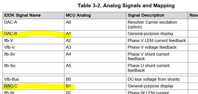
    The DAC signals that are brought out to H10 header are DAC B  & C. I think the example uses DAC-A by default, which can be changed.

    I also wanted to figure out exactly how to measure the current through the V,W,M phases on the IDDK board. The servo code provided has a current sensing block, but I'm not exactly sure how to isolate it and use it without running anything else. I need to know what physical connections need to be made, and what "build level" I am supposed to be at. Thanks in advance!

    Suggest reviewing the docs for IDDK located in the MC SDK directory: C:\ti\c2000\C2000Ware_MotorControl_SDK_4_00_00_00\solutions\tmdxiddk379d\docs

    Build levels are described in https://www.ti.com/lit/spracl1

    Best,

    Kevin

  • Hi Kevin,

    Thank you for your response. I realize that I can edit the code to output to the desired pins, but I'm not exactly sure what the syntax is to edit the said pins. I tried playing around with the demo code replacing things like DACA_BASE to DACB_BASE but that didn't work.

    I am trying to find out exactly what I need to edit, and what to edit it to, to output the desired signal out of DACB and DACC. Can you help us? Thank you!


    Kind Regards,

    Jejomar

  • Hi Jejomar,

    I tried playing around with the demo code replacing things like DACA_BASE to DACB_BASE but that didn't work.

    In the 'buffdac_ex1_enable' example this should be the only thing you need to do actually. Make sure you've changed every instance of 'DACA_BASE' in the entire buffdac_ex1_enable.c file (i.e. in the configureDAC function call as well).

    Best,

    Kevin

  • Hi Kevin,

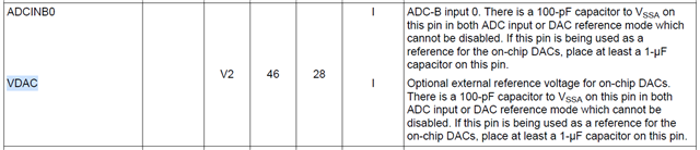
    I just did some testing and unfortunately it was not very successful. Changing the dacVal variable to check if the DAC output is changing based on the software revealed that it in fact is not. I keep reading values of around 12mV regardless of the dacVal selected. I am wondering if the reference voltage could be the issue. By default, the reference is VDAC, which - as I understand - I have no control over, so I am not sure if it is set to 0 or something which might be why I am constantly reading the same values. The datasheet specifies that the output voltage can be calculated using:
    DACOUT = (DACVALA * DACREF)/4096

    Given that by default the dacVal, which I assume is pertaining to DACVALA, is 2048, and let's assume that DACREF is 1V, that means the DACOUT should be 0.5V. I am not reading any values close to that. Where should I go from here? Am I able to change the REF voltage, or at least find where it is defined? I have no access to the other reference mode that uses ADC pins as I am working with the IDDK board, so all ADC pins are reserved.


    Kind Regards,

    Jejomar
  • Hi Jejomar,

    You bring-up a good point about VDAC, which I hadn't thought of. The VDAC signal is meant to be fed a reference voltage in this configuration. It's on the same pin as ADCINB0.

    If you aren't able to feed a source to the VDAC pin then you can change the code to use 'DAC_REF_ADC_VREFHI' instead to use VREFHI as the reference.

    Best,

    Kevin

  • Hi Kevin,

    I have finally managed so successfully output a desired voltage out of the DAC pins now that I used VREF_HI. My next step now is to write code that alters the DAC output according to current readings. I have read through the sources you directed me to, but I'm still not exactly sure how and where to start. I have different power sources, both AC and DC, to be inputs through the motor phases. I want those phases to go through the inverter, get rectified, and go out the DC output to charge a battery. While that is happening, I want the DAC pins to output in response to the current readings. Thanks again for your help!


    Kind Regards,

    Jejomar

  • Hi Jejomar,

    Ok, if you're just trying to understand how to output the 12-bit value in software you can use the DriverLib function below. Where dacVal would be whatever updated value you calculate / decide.

    DAC_setShadowValue(DACx_BASE, dacVal);

    Best,

    Kevin

  • Hi Kevin,

    I would like to know how to go about inverting two different power sources to the DC output while keeping track of each phase's current reading. Once that is done, I believe I can make some user-defined variables and functions that output DAC signals accordingly. So right now I want to figure out the inverter and current reading. Can you help us with this?


    Kind Regards,

    Jejomar

  • Hello Jejomar,

    Kevin is out of office and should get back to you at the end of the week. 

    Thank you for your patience.

    Lori

  • Hello Lori,

    Noted on this. Thank you for the update!


    Kind Regards,

    Jejomar

  • No problem - thank you for your patience.  

    Regards

    Lori

  • Hi Lori and Kevin,

    May I follow-up on this please? Thank you!


    Kind Regards,

    Jejomar

  • Hi Jejomar,

    Sorry for the delay. The IDDK platform offers three different current sensing options. Which one are you interested in using? Different methods are documented in https://www.ti.com/lit/spruiq4

    //
    // Following is the list of Current sense options
    //
    #define  SHUNT_CURRENT_SENSE   1
    #define  LEM_CURRENT_SENSE     2
    #define  SD_CURRENT_SENSE      3

    Best,

    Kevin