This thread has been locked.

If you have a related question, please click the "Ask a related question" button in the top right corner. The newly created question will be automatically linked to this question.

TMS320F28065: TMS320F28065 Debug Connection With XDS110 Debug Probe

Part Number: TMS320F28065
Other Parts Discussed in Thread: C2000WARE

Hello,

I am currently designing a small ECU with TMS320F28065 processor. I have few doubts regarding XDS110 debug probe connections as below

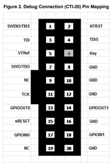
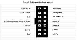
1. I am planning to put a small header on my development ECU for connecting XDS110 probe. When I studied the datasheets of processor and XDS probe then I found two pictures as below
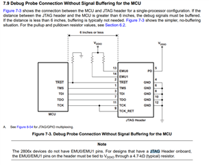
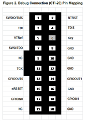
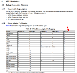
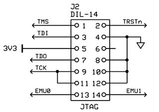
First two picture is snapshot from processor datasheet where it is seen that 14 pins are connected. Whereas in third picture (taken from XDS110 probe manual) it is seen that 20 pin connection is used for debug.

I am bit confused if it is just 14 pins of second connector that needs to be populated on my development ECU? And leave remaining pins unconnected? 

If above is not the case then what is to be connected to pins 15 to pin 20?

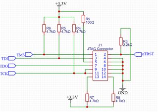
Update: the schematic in ECU for debug connection is as below:

Please suggest on this.

  • Hi Rohit,

    The XDS110 should come with a 20-pin to 14-pin converter adapter. That way you can design the header based on the datasheet. The adapter will take care of routing the proper signals from the debug probe to the board. 

    Best Regards,

    Marlyn

  • Hello Marlyn,

    Thank you for this information.

    Let me elaborate my problem in more details:

    I am making a custom board using TI TMS320F28065PZPS Microcontroller. I have taken out 5 JTAG signals i.e.TMS, TDI, TCK, TDO and nTRST. Now I want to understand where do I connect them, to 20 pin header or 14 pin header. The doubt is because there are two different meanings of the pins on these two connectors as per datasheet of XDS110 as below:

    I want to understand which connector should I consider to connect my 5 JTAG pins to and then XDS110 port. The pins on 14 pin and 20 pin are different. There are no UART pins in 20 pin but they are there in 14 pin connector. 

    The connection I did so far is as below with 20 pin made header (2 row, 2.54mm pitch):

    The ckt shows 14 pin header but in latest revision the connections are done on 20 pin connector. I am not understanding what to connect to remaining pins i.e. pin 15 to pin 20.

    Also if you have any idea about CAD details of these connectors so that I can solder mating part on my PCB.

    I hope my query is clear. 

  • Hi Rohit,

    The XDS110 User Guide provides the following table which shows the TI 14-pin adapter and the JTAG connections. You should look at the TI 14-pin adapter (which should also come with the XDS110) not the AUX Connection signal mapping.

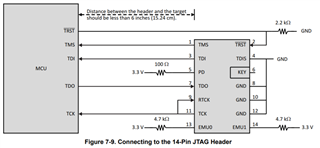
    Here is a snippet from one of our schematics that lays out the connections of this 14-pin header.

    The full schematic is shown here:

    C:\ti\c2000\C2000Ware_version\boards\ExperimenterKits\DockingStation_DIM_100pin\R3

    As far as the CAD files, there is more information here:

    https://software-dl.ti.com/ccs/esd/documents/xdsdebugprobes/emu_jtag_connectors.html#ti-14-pin-header-information 

    Please let me know if there are any additional questions.

    Best Regards,

    Marlyn

  • Alright. 

    This means The AUX (14Pin cable) from XDS110 is not to be confused with 14 Pin JTAG Connection.

    The 14 Pin JTAG connection is that additional 20 pin to 14 pin adapter that comes with XDS110. This way the 20 Pin cable coming from XDS needs to be connected to 20pin to 14 pin adapter and then to controller JTAG connections. This is clear.

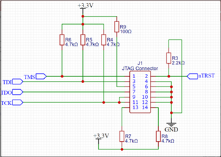
    Just last query based on above, I have finalised below schematic:

    This should be ok right?

    Kind regards,

    Rohit

  • Hi Rohit,

    This should be ok right?

    You shouldn't have a resistor between TMS, TDI, or Clock and the 3.3V rail. These connections should just go straight from the header to the MCU (same as the two diagrams you attached in the initial post). 

    Everything else looks okay. Another recommendation is the 2.2k resistor (R3) may need to be something larger like 4.7k ohms or 10k ohms. I would try 4.7k ohms and if your connection isn't stable do 10k ohms.

    Best Regards,

    Marlyn