This thread has been locked.

If you have a related question, please click the "Ask a related question" button in the top right corner. The newly created question will be automatically linked to this question.

TMS320F28335: Reading Analog Values through ADCIN Pin

Part Number: TMS320F28335

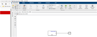
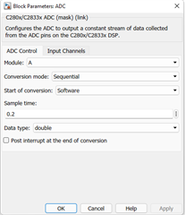
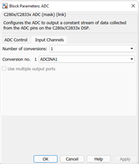
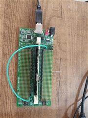
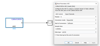
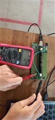
We have used the 5V pin on the Docking station to power a LED through a push switch on a breadboard. We wanted to read the analog voltage value across the LED through the ADC Pin A1. The led runs with the push-switch activation but no output is observed on the simulink scope. We have used C280x/C2833x ADC Block to read the input. (Please refer to the image). Is there any problem in our setup or the simulink model?


  • Prashant,

    Can you edit the Block Parameters as follows:

    Sample time = 0.000001

    Data Type : Uint16

    and see if this fixes things?  The min sample time if the device is clocked at max is 80ns, I'm trying 1us to give some extra charge time.  I don't think 200ms sample time is possible with the clock ratios on the device.

    Best,
    Matthew

  • Hey Matthew,

    I have changed the block parameters like you said but reading the value of A1 pin on the scope still shows zero value.

    Now for the sake of simplicity, I have directly connected the 5V output from the TI board to the A1 pin, placing the same value of sample time and data type. But still the output on the scope shows nothing. I have checked the value on the analog pin using a multimeter where it shows approx. 5V output. Am I still missing something?

  • Prashant,

    The ADC on this device has a max input of 3V. 

    If >VDDA(3.3V) is applied to a ADC input pin(or any pin) there is also a chance of damage to the device. 

    Can you try to apply 1.5V to see if the converter behaves properly? 

    Best,
    Matthew