This thread has been locked.

If you have a related question, please click the "Ask a related question" button in the top right corner. The newly created question will be automatically linked to this question.

TMS320F280025C: Controller works fine in debug mode but not in standalone

Part Number: TMS320F280025C

Hi Folks,

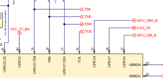
I am using the custom board and having a TMS320F280025c controller.

When I put my system in debug mode, everything works fine but in the standalone (i.e. without debugger) it's not working.

I have done the following things.

1. Disabled the watched in startup code.

2. verified VDDIO as 3.3V

3. verified XRSn as 3.3V (No fluctuations on the line)

4. Moved clock source from external to internal oscillator and VV but the result is the same(not working).

4. Checked on Development kit( TMDXCNCD280025C and docking station), works fine in both conditions

please suggest if I am missing anything to reverify.

  • Hi Amol,

    Please review and verify all the steps in the E2E below have been followed. Maybe one thing specific to verify would be the boot mode states, should both be high for flash boot mode.

    https://e2e.ti.com/support/microcontrollers/c2000-microcontrollers-group/c2000/f/c2000-microcontrollers-forum/878674/faq-flash---how-to-modify-an-application-from-ram-configuration-to-flash-configuration

    Best,

    Kevin

  • Hi Kevin, 

    Thanks for the immediate support. I have gone through the procedure and I have a query related to the Boot mode selection.

    As per the point no. 5 in "In order to convert a RAM-based application to the flash-based one, below steps are needed:" section

    Do we have to make Boot mode GPIOs(GPIO 24 and GPIO 32) to 1 if I want to do the boot from flash? (Please find the attached schematic snip for the protoboard)


    Please let me know if my understanding is correct or not.

    Regards,

    Amol

  • Hi Amol,

    They are the default Boot Mode pins so they should be pulled High/Low at start-up to match the desired mode. This can be altered by changing OTP values. I suggest reviewing section 4 "ROM Code and Peripheral Booting" of the device TRM.

    Best,

    Kevin

  • Hi Kevin,

    Thanks for the suggestion.

    I have achieved boot from flash by pulling up both the GPIOs i.e. 32,24.

    I am trying the alternate method by changing the OTP values. Below is the basic code developed, please have a look.

    main.c

    /* Address found in data sheets */
    #define BOOT_PIN_CONFG_ADD 0x0005F008
    #define BOOT_DEF_LOW_ADD    0x0005F00C
    #define BOOT_DEF_HIGH_ADD   0x0005F004

    #define BOOT_PIN_CONFG_VALUE   0x5AFFFFFF
    #define BOOT_DEF_LOW_VALUE      0x03
    #define BOOT_DEF_HIGH_VALUE     0x00

    #pragma DATA_SECTION(BootPinConfig,"boot_pin_config")
    uint32_t *BootPinConfig = NULL;

    #pragma DATA_SECTION(BootDefLow,"boot_def_data_low")
    uint32_t *BootDefLow = NULL;

    #pragma DATA_SECTION(BootDefHigh,"boot_def_data_high")
    uint32_t *BootDefHigh = NULL;

    BootPinConfig = (uint32_t *)BOOT_PIN_CONFG_ADD;
    BootDefLow = (uint32_t *)BOOT_DEF_LOW_ADD;
    BootDefHigh = (uint32_t *)BOOT_DEF_HIGH_ADD;

    EALLOW;
    *BootPinConfig = BOOT_PIN_CONFG_VALUE;
    *BootDefLow = BOOT_DEF_LOW_VALUE;
    *BootDefHigh = BOOT_DEF_HIGH_VALUE;
    EDIS;

    /* End of Main file */

    Linker File changes:

    MEMORY

    {

    BOOT_PIN_CONFG_ADD : origin = 0x0005F008, length = 0x00000002
    BOOT_DEF_LOW_ADD    : origin = 0x0005F00C, length = 0x00000002
    BOOT_DEF_HIGH_ADD   : origin = 0x0005F004, length = 0x00000002

    }

    SECTIONS

    {

    boot_pin_config       : > BOOT_PIN_CONFG_ADD
    boot_def_data_low  : > BOOT_DEF_LOW_ADD
    boot_def_data_high : > BOOT_DEF_HIGH_ADD

    }


    Please let me know if I made something wrong.

    Regards,

    Amol

  • Hi Amol,

    I will request an OTP / BOOT-ROM expert respond. I'm not as familiar with the software implementation for this.

    Best,

    Kevin

  • Can you check if the addresses  0x0005F008, 0x0005F00C, 0x0005F004 are written with the values you expect.

  • Hi Baskaran,

    These are one-time write registers, I am afraid if something goes wrong.

    Still, I'll give it a try and update you on this.

    Regards,

    Amol

  • are you able to make progress or do you still need help.