This thread has been locked.

If you have a related question, please click the "Ask a related question" button in the top right corner. The newly created question will be automatically linked to this question.

INSTASPIN-BLDC: Current feedback polarity issue

Part Number: INSTASPIN-BLDC
Other Parts Discussed in Thread: BOOSTXL-3PHGANINV, INA240, MOTORWARE, DRV8301

Hi team,

Here's an issue from the customer may need your help:

Regarding BOOST'XL-DRV8301, the detection resistance of the three-phase current is located between the lower bridge arm drive tube and GND:

The check amplifier is designed as follows:

The sense resistor P is connected to the negative side of the amplifier and the resistance N is connected to the positive side of the amplifier, which is the negative polarity connection. As described in the InstaSPIN documentation:

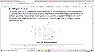
The code is as follows:

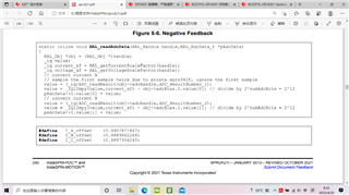
As above, although it's negative polarity connection, the offset of the current is positive and the HAL_getCurrentScaleFactor is positive.

1) If the above hardware circuit design and software calculations are used, the acquired phase current phase should be in the same direction as the motor phase current. Is that correct?

2) The negative polarity connection method is used because the sense resistor is between the lower bridge arm drive tube and GND, and the current flowing through the resistor is flowing from each phase winding, that is, the current flowing through the resistor is 180 degrees from the phase of the motor phase current, so the negative polarity connection method is used. So the polarity of the sense signal from the amplifier output is the same as the motor phase current. Is that right?

3) The typical application for detecting motor phase current using the INA240A1 in the BOOSTXL-3PHGANINV development kit is shown in the following figure:

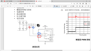
As seen in the figure above, the sample resistor is connected in a three-phase winding in a different way than the sample resistor is connected in a string between the lower bridge arm and GND. So the positive feedback connection is used in the typical application diagram here. However, the INA240 in BOOSTXL-3PHGANINV uses a negative feedback connection, as shown in the following figure:

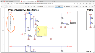
The sampling resistors are connected in parallel  in each phase of the motor. Why still use a negative polarity connection?

Could you help check this case? Thanks.

Best Regards,

Cherry

  • The phase current is bidirectional, you can use either positive or negative polarity connection, just need to set the right "sign" in  HAL_readAdcData() in hal.h file according to the current sensing circuit.

      _iq current_sf = +/-HAL_getCurrentScaleFactor(handle);

    “Thanks for your questions on our InstaSPIN solutions.  I’d like to point out that the solutions that use MotorWare are about 10 years old and haven’t had any updates in that time. We recommend our customers use our latest generation of devices which are supported for InstaSPIN-FOC, other sensorless techniques, and sensored servo control through C2000Ware-MotorControl-SDK

  • Hi,

    Thanks for your help.

    The customer would like to figure out the relationship between amplifier output and actual current, so could you help elaborate on the following questions:

    1) Does the ina240 in the gallium nitride development kit have a 180-degree phase difference or the opposite polarity when compared to the typical circuit on page 1 of the ina240 data sheet?

    2) If in a gallium nitride development kit, a Hall sensor or a fluxgate sensor is used for phase current acquisition, is the detection output of the sensor the same or 180 degrees difference between the detection output of the ina240 in the development kit?

    3) Is the current acquisition software handling of the gallium nitride kit using negative polarity like the drv8301 development kit, i.e. offset positive, current-positive? Or should we use the corresponding offset negative, current-sf negative positive polarity?

    Thanks and regards,

    Cherry

  • Not fully understand the customer's questions above. There is no any phase shift using the inline shunt current sensing with INA240.

    As mentioned above, just need to change the "sign" depends on the current sensing circuit, and don't need to make any other changes. The sign should be negative for BOOSTXL-3PHGANINV.

      _iq current_sf = -HAL_getCurrentScaleFactor(handle);