This thread has been locked.

If you have a related question, please click the "Ask a related question" button in the top right corner. The newly created question will be automatically linked to this question.

TMS320F28335: Problem with the GPIO output

Part Number: TMS320F28335


Hello E2E,

Please help our customer with the problem encountered with the TMS320F28335 GPIO, here is the full query:

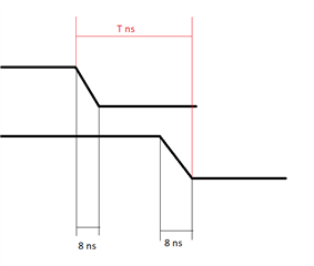
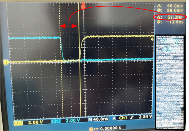
Recently, I find something unexpected about the GPIO delay. For example, when I try to change two GPIO outputs successively shown below, there will be a 50ns delay between two GPIO, which could be observed from the Oscilloscope. (Note: The system clock is 150M, so the system period is about 8.3ns) Why does it take so many system clocks to set or clear GPIO? 
 
     GpioDataRegs.GPACLEAR.bit.GPIO4 = 1; 
     GpioDataRegs.GPASET.bit.GPIO5 = 1; 
 
In addition, when I write code like:
 
     while (!GpioDataRegs.GPADAT.bit.GPIO2);
     GpioDataRegs.GPACLEAR.bit.GPIO4 = 1;
There will be a 150ns delay from GPIO2 input to GPIO4 output, which is totally out of my expectation.
 
Could you help me with these two problems?

Regards,
Carlo

  • I will loop in the expert on this device.

    Nima

  • Hello,

    I see the code that's tested, but I have a few questions. When it says "50ns delay between two GPIO", is this measuring time between the rise of both GPIO, or how long it takes for the GPIO to rise? If it's the former, this could be because of a number of reasons, the most significant being where the code is compiled. If the code is running on FLASH, there is at least 5 wait states per cycle, which can lag the time between instructions. If the code is running on RAM, you can show the disassembly to maybe help clarify what's happening on the CPU level.

    The code with the while loop will inherently be longer because of the way the code is run, where the pipeline needs to be flushed if the conditional is not met, etc. This is C code, and inherently will not be as optimized as assembly. Please let me know if you discover what the timing of 50 ns and 150 ns refers to.

    Omer

  • Hi Omer,

    Please see the response from our customer:

    It refers to the measuring time between the rise of both GPIO, which could be found in the attachment. In addition, I can briefly describe my demands for DSP, that I need to control PWM according to two input pulses shown in the attachments. Therefore, I am very cared about the delay for GPIO input captures and output generations. It seems that there are delay problems for both GPIO input and output. I know the interruption ways to detect GPIO and generate PWM will be more time-consuming. If possible, is there any best solution to realize the fast GPIO detection and generation?

    Regards,
    Carlo

  • Hi,

    To clarify, the datasheet for the F2833x devices says in section 7.9.4.1.1.1 (PDF page 50), that there is a 8 ns maximum time for the GPIO to rise/fall. This does not mean that it takes 8 ns for one GPIO to go fall and another to rise, it means that when a GPIO goes low or high it should take 8 ns maximum for the single transition to occur. Therefore, the 50 ns delay is appropriate, given what I said in my previous post on FLASH and additional assembly instructions because of the C compiler.

    To utilize the GPIO with the ePWM for efficiency, you could set up the ePWM Trip Zone submodule to have direct effect of the GPIO on the ePWM without latency of an ISR. If you want, I can loop in an ePWM SME to help explain this in further detail.

    Best regards,

    Omer Amir

  • Hi Omer, 

    Thanks a lot! I have checked the code and GPIO again according to your advice. There are several further questions:

    ePWM:

    1. Although ePWM is the best way to control PWM which I have also used normally, it can't deal with the practical situation I encounter now, where the PWMH and PWML period are both determined by the input pulse, shown in the previous figure. So do you think ePWM has such kind of capability to generate PWM only based on input trigger signal?  

    Code time:

    2.1 The maximum rise/fall time 8ns has no effect on the 50ns delay, because the time I measured is based on the start point where the GPIO begins to rise or fall, shown in the previous figure;

    2.2 I have checked the disassembly, the code 'GpioDataRegs.GPACLEAR.bit.GPIO5 = 1' takes 4 system clocks measured by CCS, which includes two pieces of assembly code. Therefore, it seems to take 4*6.3ns.

    2.3 I am confused about 'If the code is running on FLASH, there is at least 5 wait states per cycle', so do you mean there are 5 more system clock to be consumed for every piece of assembly code? If so, that will be very wired.

  • Hello Wang Lei,

    1. I can loop in an ePWM expert to better answer this question.

    2.1 I'm not sure what I'm communicating is clear, so I've inserted a diagram below that shows what I mean. The rise/fall time is supposed to be a maximum of approximately 8 ns according to the F2833x datasheet (see the section and page number listed, also depicted below). If this is what you're doing, please show me the oscilloscope image where this transition is taking 50 ns. It says nothing about the time T in the diagram, as this depends on how/where the code is compiled (the toggling time listed below is the time to toggle a single GPIO, not turning one high and another low).

    2.2 The line 'GpioDataRegs.GPACLEAR.bit.GPIO5' is the most optimized instruction for clearing a GPIO bit, as you've seen, but this still requires more than 1 cycle because of the instruction set.

    2.3 Yes, running code on FLASH is inherently slower. Looking at the datasheet for the device, this is what I found (see table 7-4 in section 7.9.7.5 of the datasheet, on page 95); at a frequency of 150 MHz for the system clock, there are 5 page/random wait-states.

    Let me know if there are further question about this, and I will make sure to loop in the ePWM expert to help answer your first question.

    Best regards,

    Omer Amir

  • Hi Wang Lei,

    1. Although ePWM is the best way to control PWM which I have also used normally, it can't deal with the practical situation I encounter now, where the PWMH and PWML period are both determined by the input pulse, shown in the previous figure. So do you think ePWM has such kind of capability to generate PWM only based on input trigger signal?  

    Unfortunately, there is no inherent way to change the output of the PWM based on an input pulse. You would need to implement a work-around to change the PWM output based on the pulses themselves. Another option for this is implementing external interrupts for these GPIOs and then within the ISRs do an action qualifier continuous software force  or trip zone software force to alter the PWM output. 

    Best Regards,

    Marlyn

  • Thanks for your verifications. As I expected before, there is no such function for the embedded ePWM. As for the way of interrupts, it will lead to an apparent delay for the PWM triggered by input pulses.

    Best Regards,

    Lei

  • 1. Thanks for your passional manner, patient answer.

    2. I have reclarified that below:

    3. Yes. The maneuver of GPIO registers seems to be slower than that of other registers. 

    4. I think the wait-states are not followed by every instruction, otherwise the DSP running on Flash will be very slow. In general, is the code running on Flash slower than that on ROM, am I correct? 

  • Hello Lei,

    2. According to the diagram, the 50 ns is still not asserted to be anything according to the datasheet, only the transitions, so this seems appropriate if running on something like FLASH (the only way to fix this would be to run the program on RAM and double check that the disassembly that gets generated is as optimized as it could be).

    4. The wait states are indeed on every instruction, if you're running your program from FLASH. This is because every instruction needs to be fetched from FLASH, and so incurs that wait-state penalty. To answer your question, yes in general FLASH is usually slower than RAM/ROM I believe

    Best regards,

    Omer Amir

  • Thanks a lot. After a discussion with you, it seems that I have to use FPGA or CPLD. I really appreciate your help, you can close the case now.