This thread has been locked.

If you have a related question, please click the "Ask a related question" button in the top right corner. The newly created question will be automatically linked to this question.

TMS320F28069: How to build release version of code

Part Number: TMS320F28069
Other Parts Discussed in Thread: C2000WARE, MOTORWARE, C2000WARE-MOTORCONTROL-SDK, , , DRV8301-69M-KIT

Hello,

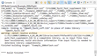
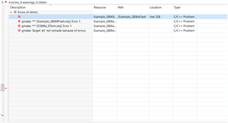
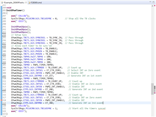
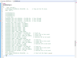
I have a project in which I started using the example project "Example_2806xScia". I modified it to use Scib, rather than Scia. I also added a layer to accommodate the SLIP protocol. The original project had only a Debug Configuration, no Release Configuration. So it runs fine in Debug mode, but when I remove power and restart the micro, nothing happens, unless I connect the debugger (Code Composer) and run it from there. I've read in multiple documents that Code Composer automatically generates both a Debug and a Release configuration. I have not seen this. I've looked at every example in C2000Ware and in Motorware, and cannot find one project where both of these configurations are present. I thought maybe if I could see the Properties of both types of configurations, and see the files in the Release & Debug folders, that I might get some idea just what the differences are between the two. That way I could setup the Release version so that it acts like a Release (i.e. I could load it on the micro, and it would run independently of the debugger). I've also read that release builds often employ Optimization (level 2 seems to be recommended), and that "Symbolic Debug" is disabled. Well I can turn on Optimizations, but I can't for the life of me find anyplace where I can disable Symbolic Debug. In any case, I feel like these can't be the defining characteristics of a release build. There must be some fundamental "switch" that differentiates between debug and release. It appears that the documentation just assumes that you know how to do this. I would love a step by step description of how to turn a Debug only project into one from which I can generate a Release build.

Thanks in advance for any help.

Best Regards,

Dave

  • Hi Dave,

    I am having your post rerouted to the C2000Ware-MotorControl-SDK team to further answer your questions.

    As far as Debug and Release versions of examples, it should be noted that there should be a few examples available in the driverlib directory of C2000Ware that includes both versions under the build configurations. It is typical that only Release versions are supported for public releases. In motor control apps, one of the key feature of Release configs is that Release versions tend to be setup to run from Flash versus RAM. Which from what I understand is what you desire in your case. If so, you can check out the flash examples for the F28006x devices in C2000Ware on how to configure the project to run from FLASH. It will also have a FLASH configuration.

    Here is an app note that explains how to run an example from Flash: https://www.ti.com/lit/an/spra958l/spra958l.pdf?ts=1650659544854&ref_url=https%253A%252F%252Fwww.google.com%252F 


    Regards,

    Ozino

  • Hi Ozino,

    I took a look at the examples in the driverlib directory, and there are indeed both Debug and Release versions in many of these. However, the properties are exactly the same for Debug and Release. The files contained in the Debug and Release folders are named exactly the same, but the ones in the Release folder are somewhat smaller. I can't look at the contents of these files, though, so I can't discern whether the fundamental difference between Debug and Release is contained in them. And even if I could see the contents, it seems unlikely that building a release application would involve manually going in and changing the file contents.

    The Motorware examples contain only the "Release" version (which, oddly enough, is runnable from the debugger). There is no corresponding Debug folder, which would allow me to see the differences between the two.

    I don't necessarily desire to run this program from FLASH. I just want it to run independently of the debugger. I need a "release" version. If that requires me to run from FLASH, then so be it, but in many respects I think I'd rather use RAM - it's typically faster.

    I've used other microcontroller / IDE combinations where it was obvious, even easy, to create a release version that would run on the micro independently. Here, the whole process seems shrouded in mystery.

    Thanks for your help.

    Best Regards,

    Dave

  • I hate to be a pain, but does anyone out there know how to create a release, an executable, a stand-alone application? I suppose I could think of a few more synonyms, but I'd rather be loading my micro with a program that's not dependent on the debugger for operation. Am I asking the question wrong? Am I, in fact, asking the wrong question?

  • In the document spru509.pdf (Code Composer Gsetting Started Guide), it states:

    "The new project and first project configuration (in alphabetical order) become the active project, and
    inherit the TI-supplied default compiler and linker options for debug and release configurations."

    I used an existing example to start, and altered that to suit my requirements, so the automatic creation of Debug and Release mentioned above did not occur - only the Debug build is created.  The document mentioned above was written for Code Composer v 3.3, so that feature may no longer be available. Could someone tell me what the default compiler and linker options for the release configuration typically are?

    I've tried creating a new project from scratch, and a release folder is not automatically created, just Debug, so I still have no idea in what way a Release version might be different.

    Thanks,

    Dave

  • There's no set definition of what a "debug" or "release" should be. Generally, when we name a build configuration "debug" it means means no optimization and if the application supports it, enabling other debug features like asserts or profiling hooks. In a "release" build configuration we'd probably turn up optimization to at least level 2 if not higher and remove any debug features that may impact performance/code size.

    It's totally up to you how you define your build configurations though. If you just want one build configuration that you use in all circumstances, that's fine too. It's possible older versions of CCS or the compiler enforced some difference, but that doesn't seem to be the case in the latest.

    When it comes to booting from flash standalone vs running from the debugger, "release" vs "debug" as I've described them above don't necessarily matter. It's more important that you're using a flash linker command file, that you've set up the code start branch at the correct entry point, that you have "ramfuncs" set up for code that needs to be executed from RAM, that you've set up the boot pins on your board correctly, etc...All of that should be described in the document linked above by Ozino.

    Also check out the "flash_f28069" example. I believe it's supposed to have all those things set up so you can boot it from flash standalone as well.

    Whitney

  • Hi Whitney,

    Thanks for your reply. So, If I add Optimization, and disable Symbolic Debug, load the program onto the device, and cycle power, the program should run on the target independently of the debugger. Problem is... it's not doing that. What are the steps for setting everything up so that I can run an application without the debugger involved?

    Thanks,

    Dave

  • Hi Whitney,

    More questions. The document that Ozino provided states that "this application report applies only to DSP/BIOS."

    I've read that " in August 2010, DSP/BIOS was renamed SYS/BIOS to reflect its support for microcontrollers beyond DSPs."

    I'm not sure which type of project this is.

    How do I find out?

    What if it turns out to be SYS/BIOS? Is there another Application Note that covers that?

    Thanks,

    Dave

  • You're using a C2000Ware example as your starting point, right? None of our C2000Ware examples use any RTOS, so you can just follow the non-BIOS parts of that document.

    Which linker command file are you using in your project? Is it one for a Flash configuration with a codestart section placed at the flash entry point? Do you have F2806x_CodeStartBranch.asm in your project?

    Do you have any code in "ramfuncs" in your project? Do you have a call to memcpy in your code to copy the ramfuncs from Flash to RAM before you try calling any of the ramfuncs functions?

    How are the boot pins configured on your board?

    Whitney

  • Hi Whitney,

    The linker command file is 28069_RAM_lnk.cmd - no mention of FLASH in the file. Is there a corresponding FLASH linker command file that I should load? If so, where can I find it,  and should I remove the RAM link cmd file?

    F2806x_CodeStartBranch.asm is present and part of the project.

    There is a reference to ramfuncs in the 28069_RAM_link.cmd file as follows:

    ramfuncs         : > RAMM0,      PAGE = 0

    There's also the following in F2806x_SysCtrl.c:

    //  *IMPORTANT*
    //  IF RUNNING FROM FLASH, PLEASE COPY OVER THE SECTION "ramfuncs"  FROM FLASH
    //  TO RAM PRIOR TO CALLING InitSysCtrl(). THIS PREVENTS THE MCU FROM THROWING
    //  AN EXCEPTION WHEN A CALL TO DELAY_US() IS MADE.
    //
    #pragma CODE_SECTION(InitFlash, "ramfuncs");

    And some actual code - F2806x_usDelay.asm - is run from ramfuncs.

    I have not implemented memcpy for moving code between FLASH and RAM at all yet.

    I've seen the examples in the document SPRA958L, and am going to give it a try today.

    I have no idea how the boot pins are configured on my board. I just hope it doesn't involve a hardware change.

    I've acquired Application Note spraca2a.pdf "TMS320F28x Boot Features and Configurations".

    Haven't read much of it yet, but it appears to deal with the boot pins. Is that a good source?

    Any other advice to smooth the way? This is a relatively simple program, just serial comm, using the SLIP protocol,

    so I don't think I need to get too fancy, placing sections of the actual operating code into RAM, or anything like that.

    I will, eventually be merging this with motor driver code, specifically InstaSpin, so there may be a reason for optimizations of that sort then.

    Thanks,

    Dave

  • Try importing the flash_f28069 example I mentioned earlier. It should contain a flash cmd file and a memcpy you can use as an example.

    Are you using your own board or one of our EVMs? Our controlCARDs and LaunchPads usually have a set of switches to change the boot mode--info on those switches can be found in the user's guides for those boards. spraca2 should be a good source for how the boot mode select pins work and the boot ROM flow. There's also a Boot ROM chapter in the F2806x TRM that may have some additional device specific info.

    Whitney

  • Hi Whitney,

    I've designed a custom board, based heavily on the DRV8301-HC-EVM . Unfortunately I didn't include SW1; at the time I couldn't see the use of it. Since all the boards I've got are going to run from Flash, I could just tie the appropriate pins High or Low with blue wires. Then incorporate those changes on the next board spin. On the evaluation board, GPIO34 and TDO (GPIO37) can be tied High or Low, depending on the state of the switch. Does TDO serve double-duty somehow as a boot pin?

    Evidently, the following boot modes are available for the F28069:

    0. Parallel boot
    1. SCI boot
    2. Wait boot
    3. Get boot/flash

    Is 3 (both GPIOs high) the setting that I want? The document Ozino pointed out to me says to configure for ‘Jump-to-Flash’ mode, which isn't mentioned specifically, even in the expanded list of boot modes (available if using 4 boot pins).

    Thanks,

    Dave

  • Yes, you've got it. Setting both GPIOs high should put you in "Get" boot mode which will act as Flash boot until you've programmed the device OTP to tell it otherwise.

    Whitney

  • Hi Whitney,

     I went through the document "Running an Application from Internal Flash..." from start to finish, and implemented everything that (I think) applies to my situation.

    In Code Composer, if I go to Run --> Load and select Example_2806xScib_FFDLB, I get the same response as ever, as though I were in Debug mode. It loads the program and runs, but when I cycle power, nothing happens.

    If I go to Run --> Load --> Select Program to Load, and try to load the Example_2806xScib_FFDLB.out file that way, Code Composer tells me:

    "Load program error

    Multiple debuggable cores detected"

    I suppose I'm still missing something. Should I target a particular "core"? If so, how?

    Could this be related to the fact that the default boot pins are GPIO34 and GPIO37, but GPIO37 is also TDO?

    Should I select some GPIO pin other than pin 70 (GPIO37/TDO)?

    Thanks,

    Dave

  • You can load the .out like you would for debugging, then disconnect the debugger, set up your boot pins, and power cycle to see if it runs.

    If you want to then connect to the device to see where its stuck in the code, you need to do it in a way that doesn't cause a debugger reset, so you can preserve the state for debugging. One way is to set up your debug configuration as shown in this video. If that doesn't seem to work, you can also create a new ccxml file for your device, but edit it so that it doesn't use a GEL file like I showed in this thread.

    I'm not sure what would cause that "multiple debuggable cores" issue. When you're connecting to the device and loading the code, make sure you only have the C28x line selected in the Debug panel and not both the C28x and the CLA.

    Whitney

  • Hi Whitney,

    I tried loading the .out as described in the first line of your reply above. It acts just like it always did. Runs when debugger is calling the shots - nothing when I try to run independently. I'll give yor other suggestions a try presently.

    Is it ok to have both the boot pins tied high (through a resistor) all the time?

    Should I select some GPIO pin other than pin 70 (GPIO37) for a boot pin, since it's also TDO?

    Thanks,

    Dave

  • Hello Dave,

    Whitney will be out of office for several days. In the mean time I can try to help you or connect you with somebody that can.

    I'm reviewing the thread here. To answer some of your questions.

    Is it ok to have both the boot pins tied high (through a resistor) all the time?

    Generally yes. As long as the pull-up resistor is no "too strong", it will not interfere with the function of the pin once your application takes over. What resistor value are you using in your board?

    Should I select some GPIO pin other than pin 70 (GPIO37) for a boot pin, since it's also TDO?

    There is note in the F28069 data sheet that mentions GPIO37/TDO cannot be used for boot mode selection *if* the debug probe is connected. Have you tried to boot your board with the debug probe fully disconnected?

    If I go to Run --> Load --> Select Program to Load, and try to load the Example_2806xScib_FFDLB.out file that way, Code Composer tells me:

    "Load program error

    Multiple debuggable cores detected"

    I suppose I'm still missing something. Should I target a particular "core"? If so, how?

    There is an E2E post on this topic here: https://e2e.ti.com/support/tools/code-composer-studio-group/ccs/f/code-composer-studio-forum/838505/ccs-tms320f28069m-load-program-error-and-no-show-of-value-in-expression-in-debug-in-ccs-9-01

    May I ask why you want to use the Run -> Load -> Select Program to Load method?

  • Hi Gus,

    Thanks for the reply. I hope Whitney's on a fun vacation!

    As long as the pull-up resistor is no "too strong", it will not interfere with the function of the pin once your application takes over. What resistor value are you using in your board?

    I tried a 3.3k, but realized that I'd already tied the TDO pin Low through a 3.3k, as part of the original design. This resulted in 1.7V or so at the pin. So I changed it to 560 ohm. Now I'm seeing 2.8V, which should be considered a "High".

    Have you tried to boot your board with the debug probe fully disconnected?

    Tried it just now, after reading your reply. Doesn't appear to make a difference. But once I'm done writing this I'll try reloading the program, and then removing the debugger (XDS110), then booting.

    May I ask why you want to use the Run -> Load -> Select Program to Load method?

    I was just tryin everything.

    Thanks,

    Dave

  • Dave,

    Follow up question, what are you doing with the TRSTn pin on your board? It should be pull down with a resistor to disable the debug logic when the probe is not attached.

  • Hi Gus,

    Here's a screenshot of the reset ckt:

    I can remove the pull-up, if that'll help.

    Thanks,

    Dave

  • Hi Gus,

    I tried removing the pull-up. The XDS110 debug probe wouldn't even connect without it (it's back in there and connects now). So then I tried loading the program as usual (using the little 'bug' icon), stopping the debugger, removing power, attaching the *TRST to digital ground, and reapplying power. This would presumably ensure that the debug logic was not enabled. I still can't get any action out of this thing without the debugger involved.

    Thanks,

    Dave

  • Dave,

    tried removing the pull-up. The XDS110 debug probe wouldn't even connect without it

    In this test, you removed R51 and left the R22 pull-down on? That shouldn't have stopped the debug probe from working. That is odd. Note that you don't want to connect TRST directly to GND since the debug probe will actively drive that pin.

    I still can't get any action out of this thing without the debugger involved.

    I guess have you verified your code is actually running from internal flash? You can review your map file to see if the flash addresses are being filled or you can also just stop your code using CCS and see which address the device is running from by looking at the PC (CPU registers) or the disassembly window (View>Disassembly).

  • Hi Gus,

    Yes - I removed the pull-up and left the pull-down in circuit. I put the pull-up back in after not being able to connect. I didn't connect *TRST directly to ground while the debug probe was connected. I loaded the code onto the micro using the XDS110, stopped debugging, turned everything off, disconnected the debugger, grounded the *TRST pin with a temporary clip-lead jumper, then reapplied power. Seems like that should work.

    There is note in the F28069 data sheet that mentions GPIO37/TDO cannot be used for boot mode selection *if* the debug probe is connected. Have you tried to boot your board with the debug probe fully disconnected?

    How can I verify code is running from internal flash, review the map file, or stop code, if I don't connect the debug probe? Should I boot it and then connect the debugger? Is hot-plugging like this advisable? Should I just go ahead and change the boot pin from GPIO37 to something else? Although it seems like if it was chosen as the default it should be safe to use.

    I can see communication between the motor control board and the LCD when actively debugging. I can stop debugging and leave the debugger connected, and it still operates as I expect. I can even disconnect the XDS110 and everything's fine. But after I cycle power, there is no communication. It seems like it doesn't know where to start.

    Thanks,

    Dave

  • Dave,

    TRST/JTAG: Thanks for clarifying. It still doesn't make sense that the debug probe was not able to communicate with the pull-up removed. If you can share more of your schematic, specifically the JTAG design, we can take a closer look. It is a little puzzling that you added both a pull-up and pull-down to the TRSTn pin in your design. Our datasheet and EVMs call for a pull-down resistor only.

    Flash Booting: Please allow me to explain. The map file gets generated during the compilation/linking process. It is a file stored in the same project directory as your executable (.out). Debug probe access is not required, you can open this file straight from your PC using any text editor or CCS. The map file will tell us how your code is being allocated in the MCU's memory. If the flash sections are empty (i.e. usage = 0) then we'll know your code is not getting linked to flash and would explain why the flash boot fails at power up, i.e. there is no code in flash!

    Alternatively, you can bring up your code using CCS and the debug probe. Halt execution at some convenient point. Then use CCS to check the program counter (PC) or use the CCS disassembly window to see what address your code is getting executed from. You can check if the address is a flash address. The debug probe stays connected the whole time.

    Here are a couple of videos for your reference:

    https://www.youtube.com/watch?v=uLHVtBjWSUQ

    https://www.youtube.com/watch?v=LwxwJjq2IEg 

  • Hi Gus,

    I watched the video that Whitney linked, above. Went into Debug Configuration, selected "Enable Real Time Mode", and "Load Symbols Only". I ran the dbugger and checked out the program counter (halted at 0x3F402C, while Flash is from 0x3E8000  to 0x3F7FF8). It's definitely running from Flash, so at least that worked. My board communicates with the LCD board as expected. However, a power cycle has the same results as before.

    I'll send you the schematic in a little while...

    Thanks,

    Dave

  • Hi Dave,

    Thanks for sharing the schematics via private message. I'm following up with a colleague that is more familiar with this device about next steps. I will get back to you asap.

  • Dave,

    As discussed, modify your code to trap operation right after entering main() & continuously toggle a GPIO which you can monitor using a scope. Load your code to flash on a TI EVM and boot the EVM in flash boot. If the code boots correctly, then there could be an issue with your HW.

    As suggested by Whitney before, you can also import the flash_f28069 project and run it on a TI EVM first to verify it can boot. Then try to run it on your HW.

  • Hi Gus,

    I've tried the suggestions in your first paragraph, above.

    I put the following at the very beginning of main():

       asm(" EALLOW");
       GpioCtrlRegs.GPAMUX1.bit.GPIO12 = 0; // Set GPIO12 as GPIO
       GpioCtrlRegs.GPADIR.bit.GPIO12 = 1; // Set GPIO12 as Output
       asm(" EDIS");
       for(;;)
       {
           asm(" EALLOW");
           GpioDataRegs.GPATOGGLE.bit.GPIO12 = 1; // Set GPIO12 to toggle everytime this line is encountered
           asm(" EDIS");
           DELAY_US(10000);
       }

    I've loaded the code to Flash on my DRV8301-HC-EVM evaluation board.

    If I just use the Debug button, it loads, but the "Run" button is not available, and I see the following errors:

    C28xx: Flash Programmer: Warning: The configured device (TMS320F28069), does not match the detected device ().   Flash    Programming operations could be affected. Please consider modifying your target configuration file.
    C28xx: Failed CPU Reset: (Error -1041 @ 0x0) The debug probe reported an error. Confirm debug probe configuration and connections, reset the debug probe, and retry the operation. (Emulation package 9.3.0.00058)
    C28xx: GEL: Error calling OnPreFileLoaded(): Reset failed: retcode=-1
    C28xx: Failed CPU Reset: (Error -1140 @ 0x0) Lost debug connection to device. Reset the device, and retry the operation. If error persists, confirm configuration, power-cycle the board, and/or try more reliable JTAG settings (e.g. lower TCLK). (Emulation package 9.3.0.00058)
    C28xx: Error occurred during flash operation: CPU Reset error. Error code -1
    C28xx: Failed CPU Reset: (Error -1138 @ 0x0) Device refused to allow debug mode. Power-cycle the board. If error persists, confirm configuration and/or try more reliable JTAG settings (e.g. lower TCLK). (Emulation package 9.3.0.00058)
    C28xx: Error occurred during flash operation: CPU Reset error. Error code -1

    The first one seems interesting. It's telling me that the micro is not an F28069. While that may not be true, generally speaking, since it's a member of the F28069 family, it is true strictly speaking, since it's an F28069M.

    I'm going to look around for a command file that applies specifically to the M variant.

    When I go through the more manual procedure of

        Launch Target Configuration

        Select CPU and Connect

        Run --> Load Symbols,

    "0x3FF75B  (no symbols are defined)"   appears under the selected CPU, and a tab appears with the following message:

          Break at address "0x3ff75b" with no debug information available, or outside of program code.

    If I just charge ahead after this and try to Run the program, the break-point is not recognized, and a pause, results in the same "Break at address" message as above, so I can't debug the thing.

    Thanks,

    Dave

  • Hi Gus,

    I did find a cmd file for the TMS320F28069M specifically, actually two:

    f28069M.cmd and

    f28069M_ram_lnk.cmd.

    That evidently isn't the problem (see previous post).

    I tried each, in isolation, with the same results as before (this is with the EVM).

    It appears, though, that the issue is not with the hardware.

    The symptoms are slightly different, but I'm having similar problems with the EVM as well.

    The Debug probe is one significant difference. The DRV8301-HC-EVM has the XDS100v2 built in.

    There is a JTAG port, but I can't connect using it with the XDS110 (I'm half tempted to put a pull-up on the *TRST line).

    Well, that's where things stand right now. I'll be in meetings from 12:30 'til 3:00. Maybe we can talk after that.

    Thanks,

    Dave

  • Hi Gus,

    Tried running the flash_f28069 project, but the compiler keeps throwing an error that it won't specify. There's an error marker to the left of line 305 in the subroutine InitEPwmTimer. I thought I could comment out that line, but the error marker persisted - on the line that was commented out! I can comment out any and all lines in the subroutine. The error moves around in InitEPwmTimer, until I remove the whole subroutine. Then the error marker just moves to the next function - the interrupt service routine "epwm1_timer_isr". Very strange behavior.

    Dave

  • Dave,

    You probably have the DRV8301-69M-KIT, which includes the TMDSCNCD28069MISO control card. You can double check the labeling on the controlCARD to be sure. That control card does not support JTAG access through the kit base board, you can only connect to it via the USB port on the controlCARD. This is why the XDS110 was not able to connect it. It is worth noting that the controlCARD has an XDS100v1 built in (not v2). 

    Regarding the command file, if you look at the flash_f28069 example project, you will see that it includes the F28069.cmd file. In that command file you can see that it placing sections like .text in flash and it also includes the ramfuncs section which is loaded to flash and later copied to RAM. I'd recommend you import this project into CCS and run it on the TI kit.

     C:\ti\c2000\C2000Ware_4_01_00_00\device_support\f2806x\examples\c28\flash_f28069

  • Hi Gus,

    Regarding the command file, if you look at the flash_f28069 example project, you will see that it includes the F28069.cmd file. In that command file you can see that it placing sections like .text in flash and it also includes the ramfuncs section which is loaded to flash and later copied to RAM. I'd recommend you import this project into CCS and run it on the TI kit.

    That's what I did, but the compiler keeps issuing an error (whose description is blank) that moves around, and even tags comment lines (see previous post).

    Thanks,

    Dave

  • Hi Gus,

    Regarding the command file, if you look at the flash_f28069 example project, you will see that it includes the F28069.cmd file. In that command file you can see that it placing sections like .text in flash and it also includes the ramfuncs section which is loaded to flash and later copied to RAM. I'd recommend you import this project into CCS and run it on the TI kit.

    That's what I did, but the compiler keeps issuing an error (whose description is blank) that moves around, and even tags comment lines (see previous post).

    Strangely enough if I use EALLOW and EDIS, rather than asm(" EALLOW"), in InitEPwmTimer it will highlight those as errors and the mystery error disappears.

    I'm pretty sure I haven't changed anything in the flash_f28069 example project, but could you send me a copy of your version of it? I'll see whether that compiles here.

    Thanks,

    Dave

  • Dave,

    These problems are definitely very strange. I'm not quite sure what could be the problem. It may help to send a screenshot of the errors you are seeing. 

    Here I'm listing the steps I am taking to import and build the project. Note I am using CCSv11.1 (Help>About)

    1. File>Switch Workspace>Other

    2. Make new workspace "dave_e2e" and hit Launch

    3. File>Import>Code Composer Studio>CCS Projects

    4. Navigate down to C:\ti\c2000\C2000Ware_4_01_00_00\device_support\f2806x\examples\c28\flash_f28069

    5. Hit Select Folder & select "Example_2806xFlash", check the "Copy projects into workspace" button.

    6. Project>Build Project & project builds fine (not there is a linker warning about a missing library, but I think we can ignore that for now).

    On step 5 it is important to "copy" the project in the workspace. If you didn't do this before, and you made any changes to the source files in the project those changes were made in the C2000ware folder. Any time you re-import the project, those changes will still be there. If you did modify the source files with any changes, I would recommend you re-install C2000ware to get the original files back.

  • Hi Gus,

    It may help to send a screenshot of the errors you are seeing. 

    The Original error shown above.

    Note error marked as line 318 ( I had to remove a lot of whitespace to get a good screenshot, but otherwise the subroutine is unchanged from the original.

    Comment out nearly everything and error marker moves, but remains in subroutine, marking a comment.

    Remove entire subroutine and error marker moves down into the next function - epwm1_timer_isr.

    I'll switch workspaces as you suggest. See if that helps.

    Thanks,

    Dave

  • Hi Gus,

    Tried the new workspace - same error. Looks like I'll have to re-install re-install C2000ware

    Dave

  • Hi Gus,

    I re-installed C2000Ware. Now I can't connect at all.

    Here's what happens when I Test Connection from Target Configurations:

          [Start: Texas Instruments XDS100v1 USB Debug Probe_0]

          Execute the command:

          %ccs_base%/common/uscif/dbgjtag -f %boarddatafile% -rv -o -F inform,logfile=yes -S pathlength -S integrity

          [Result]


          -----[Print the board config pathname(s)]------------------------------------

          C:\Users\dreagan\AppData\Local\TEXASI~1\
              CCS\ccs1031\0\0\BrdDat\testBoard.dat

          -----[Print the reset-command software log-file]-----------------------------

          This utility has selected a 100- or 510-class product.
          This utility will load the adapter 'jioserdesusb.dll'.

          An error occurred while soft opening the controller.

          -----[An error has occurred and this utility has aborted]--------------------

          This error is generated by TI's USCIF driver or utilities.

          The value is '-151' (0xffffff69).
          The title is 'SC_ERR_FTDI_OPEN'.

          The explanation is:
          One of the FTDI driver functions used during the connect
          returned bad status or an error. The cause may be one or
          more of: no XDS100 is plugged in, invalid XDS100 serial number,
          blank XDS100 EEPROM, missing FTDI drivers, faulty USB cable.
          Use the xds100serial command-line utility in the 'common/uscif'
          folder to verify the XDS100 can be located.

          [End: Texas Instruments XDS100v1 USB Debug Probe_0]

    Note: I specified XDS100v1, but the same thing happens for v2.

    Things just seem to be getting worse with every attempt at improvement...

    Dave

  • I re-installed C2000Ware. Now I can't connect at all.

    Did the example code build ok? Or are you still seeing weird compiler issues?

    Btw, on the error moving around. I would not push too much emphasis on that unless you are rebuilding the code each time to see if the error moves around.

    What are you connecting to here?

  • By the way, the whole program is riddled with errors, so I can't compile either. There are no paths to the include files, like headers, etc.. With the old version of the project, if I look under Properties --> Build --> C2000 Compiler, there's a whole list of paths where the compiler can look for includes. In the new version under Properties --> Build there is nothing, not even a C2000 Compiler subheading.

    Thanks,

    Dave

  • Yeah - taht's when I would see it move, after every build.

    Trying to connect to the evaluation board.

  • The connection issue was my bad. I have the eval board and the XDS110 Debugger right next to each other on my bench, and picked the wrong cable to connect to the computer. Sorry, I'm just slowly descending into madness Slight smile

    Dave

  • I can add those paths. It's just a pain, especially when they were just included before...

  • Dave,

    I am really sorry you are facing these issues. I have no idea what could be going on here. Not having the build options makes no sense. Please open a new forum post, state that you cannot build or load the flash_f28069 example from C2000ware. Somebody more familiar with the software should be able to help you. Let's focus on getting this sorted out before continuing on getting your code to boot from flash.

  • I attempted to import the project into my workspace and got the following message:

          Import failed for project 'Example_2806xFlash' because its compiler definition is not available.
          Please install the C2000 v21.6 compiler before importing this project:
          - See 'Help > Install New Software' and select 'Code Generation Tools Updates' to check if this
          compiler is available through a CCS update.
          - Visit CCS App Center to get the latest compiler support.
          - Or download and install the compiler [http://software-dl.ti.com/codegen/non-esd/downloads],
          then register it with CCS through 'Preferences > CCS > Build > Compilers'

    I can get as far as 'Code Generation Tools Updates', but there is a huge list. Not sure which one to install or update.

    Which forum do you suggest?

    Thanks,

    Dave

  • There's a C2800 v21.6.0 in the list, but not a C2000 v21.6, as the message suggests.

  • When I post a new question, is there a way I can include today' posts, but not make whoever answers slog through this very long chain of communications?

  • Never mind. I just posted the new question, and kind summarized what we talked about.

  • Hi Gus,

    Enlisted the help of Ki, who in turn asked George Mock to weigh in. He figured out the apparent "compiler problem". It was something stupid that I did (of course). At one point I was attempting to merge the communications code and the motor control code into one program. This would require using the header files F2806x_Device.h and cpu.h. Some defines are repeated between them, so I commented them out in the F2806x_Device.h file. Well, in the flash_f28069 example, cpu.h is apparently not used, so commenting out those lines in  F2806x_Device.h resulted in EALLOW, EDIS, etc... being undefined. Why the error showed up pointing to code (or comments) seemingly unrelated to those commands, I don't know.

    Anyway, I'm back into loading the flash_f28069 example onto the DRV8301-69M-KIT. I'm having more or less the same problems as before - it compiles, it loads, and it runs from Flash, as long as the Debugger is present. I can stop the debugger - still running (i.e. LED3 on the TMDSCNCD28069MISO control card is blinking), then unplug the debug probe - still running, then cycle power - not running. Plug in the debug probe and reload the code, and everything runs from Flash.

    Just noticed that if I do all the above, with cycle power as the last step, then just plug in the Debug probe, then LED3 starts flashing again. So I thought maybe it's related to *TRST, or maybe the two signals that have to be high for boot mode selection (GPIO34 & GPIO37).

    If I stop the debugger, turn power off, flip both switches of SW1 to the OFF position then turn power On, LED3 is constantly Lit, meaning that GPIO34 is constantly Low - not surprising since it's tied Low for that switch position, but if the program is running that signal should be getting toggled. The pull-down is 3.3k. Doesn't seem like it would overwhelm the GPIO.

    If I'm missing something, then it's the same thing I've been missing all along.

    Thanks,

    Dave

  • Okay - got it running on the EVM. Had to turn both switches of SW1 ON (on the control card), and both switches of SW3 OFF - SW2 is "Don't Care." The only reference to changing switch positions that I've seen is at the beginning of the code for the flash_f28069 example. It says

    "//!   - Set the hardware jumpers to boot to Flash (put position 1 and 2 of
    //!     SW2 on control Card to ON position)"

    which is completely wrong.

    So, on my board, I'm going to give the following a try:

    Tie both GPIO34 & GPIO37 High, through 3.3k ohm resistors.

    Tie *TRST Low - try a 3.3k. If that doesn't work try a 10k. If that doesn't work (and in my experience the debugger won't connect), I guess I'll have to put a switch in there that will tie it high for programming/debugging, and then low for running from Flash.

    Load program into Flash.

    Turn power OFF & unplug debug probe.

    Turn power ON and it should run.

    Let me know if I'm forgetting something...

    Thanks,

    Dave