This thread has been locked.

If you have a related question, please click the "Ask a related question" button in the top right corner. The newly created question will be automatically linked to this question.

TMS320F28388D: LINKACT effective power level

Part Number: TMS320F28388D
Other Parts Discussed in Thread: C2000WARE

Hi team,

I am writing to ask the effective power level of LINKACT pin in F28388. Is it high effective or low effective? 

Could you kindly share the links of material that have this information? Not able to find such information in F28388 DS or ET1100 DS.

Regards,

Brian

  • Hi Brian,

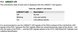
    I think it's active low based on the Beckhoff datasheet (here) and the ControlCard schematic design, i.e. No Link = HIGH state where LED is OFF. I will double confirm however and review how this can be better documented.

    Best,

    Kevin

  • Hi Kevin,

    Thanks for your kindly supply.

    Currently the observation of customer is as below: 

    Wire Plug In? Green Light(GPIO 143) Yellow Light(GPIO 148)
    No Off Constant On
    Yes but no communication Constant On Blink slowly
    Yes with communication Constant On Blink faster

    Could you help to check whether this is aligned with the normal situation? And where we could find the official definition of GPIO behavior? We looked through several different materials but not able to find any details.

    Thanks,

    Brian

  • Hi Brian, 

    The Green Light (GPIO143) behavior seems to match the LINKACT behavior from the Beckhoff datasheet, except I would have expected it to blink when there's both Link and Activity existing. Not certain why this differs right now.

    The Yellow Light (GPIO148) acts as an input from the C2000 perspective. I don't believe Beckhoff defines requirements for this LED. We connect it to LED_0 output from the PHY on the ControlCard design, below is from DP83822 datasheet. Seems like Mode 2 may be configured.

    One thing I noticed in our C2000WARE EtherCAT examples is that we configure GPIO143 and GPIO144 as invert polarity. I suppose this is done to match the LED circuit (active low).

        //
        // P0 Linkstatus and Link Active LED
        //
        GPIO_setPinConfig(GPIO_148_ESC_PHY0_LINKSTATUS);
        GPIO_setPadConfig(148, GPIO_PIN_TYPE_STD);
        GPIO_setPinConfig(GPIO_143_ESC_LED_LINK0_ACTIVE);
        GPIO_setQualificationMode(143, GPIO_QUAL_ASYNC);
        GPIO_setPadConfig(143, GPIO_PIN_TYPE_INVERT);

    Best,

    Kevin

  • Hi Brian,

    I have tested this on my side with F2838x ControlCard and C2000WARE software. I witness the below behavior:

    Link State

    GPIO143 Green (LINKACT) LED – F2838x OUTPUT

    GPIO148 Yellow (PHY LINKSTATUS) LED – F2838x INPUT

    No Link

    ON

    Off

    Link WITHOUT activity

    OFF

    ON

    Link WITH activity

    Blinking

    ON

    In conclusion, the polarity of GPIO143 Green (LINKACT) LED is actually incorrect on the ControlCard.

    Best,

    Kevin