This thread has been locked.

If you have a related question, please click the "Ask a related question" button in the top right corner. The newly created question will be automatically linked to this question.

TMS320F280049C: How to RUN/STOP 4 PWM outputs (EPWM1A/B, EPWM2A/B ) simultaneously by software

Part Number: TMS320F280049C

Two pairs of complementary PWMs, i.e. EPWM1A/B and EPWM2A/B are used in my power converter application. The variable "CmdRun" is used to control all the 4 PWMs to run when set to 1 and stop when set to 0, respectively.

Requirement 1: The start-up sequence of 4 PWMs needs to be the same every time when CmdRun=1, as in initialized configuration (EPWM1 up-count mode, EPWM1.TPRD=100, EPWM1.CMPA=10, EPWM1.TBCTR = 0, AQ set on zero while clear on CPMA event; EPWM2 up-count mode, EPWM2.TPRD=100, EPWM2.CMPA=20, EPWM2.CMPB=50, EPWM2.TBCTR = 0, AQ set on CMPA while clear on CMPB event, TBCLK=EPWMCLK=100MHz).

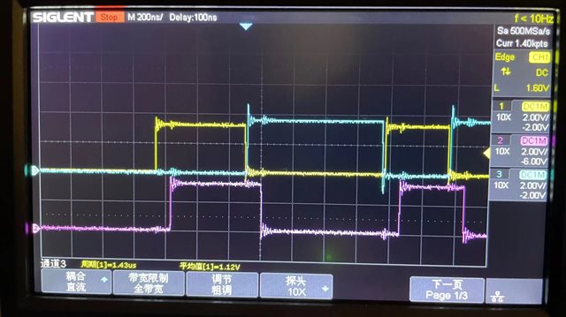
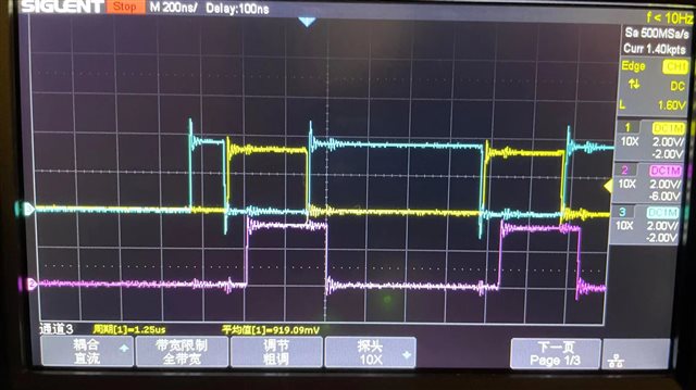
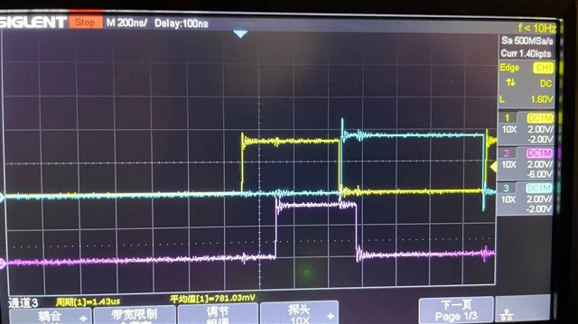
Requirment 2: For the stop sequence, when CmdRun=0, all the 4 PWMs shall be clear to low simultaneously, without even 10ns delay.

My current design is using the one-shot-trip (OST) via software. Some codes are provided as below. But it seems that the sequential execution of codes introduces some action delays. The EPWM2 will goes to run a little bit earlier than EPWM1 as it clears the OST condition before EPWM1. The EPWM1 will stop earlier than EPWM2 as it forces the OST before EPWM2. Can you give me some suggestions on how to realize the above mentioned requirements?

if (StateRun==0)
{
  if (CmdRun==1)
  {
    EPwm1Regs.TBCTL.bit.SWFSYNC = 1; // Force the TBCTR to reset.
    EALLOW;
    EPwm2Regs.TZCLR.bit.OST = 1; // Clear the one-shot trip (OST) condition.
    EPwm1Regs.TZCLR.bit.OST = 1; // Clear the one-shot trip (OST) condition.
    CpuSysRegs.PCLKCR0.bit.TBCLKSYNC = 1; // All ePWM time-base clocks are started with the rising edge of TBCLK aligned.
    EDIS;
    StateRun = 1;
  }
}
else
{
  if (CmdRun==0)
  {
    EALLOW;
    EPwm1Regs.TZFRC.bit.OST = 1; // Force a one-shot trip (OST) via software. Q1 first OFF.
    EPwm2Regs.TZFRC.bit.OST = 1; // Force a one-shot trip (OST) via software.
    CpuSysRegs.PCLKCR0.bit.TBCLKSYNC = 0; // The time-base clock of all ePWM modules is stopped.
    EDIS;
    EPwm1Regs.TBCTL.bit.SWFSYNC = 1; // Force the TBCTR to reset.
    StateRun = 0;
  }
}

  • One alternate way to look at this would be to assign a common trip signal to both the PWM modules. Now, this is possible using TZ1-3 and Digital Compare events.

    The idea will be to configure TZ1 (Trip zone input signal) to trip both EPWM1 and 2. TZ1 signal will have to be tied to a GPIO using input X-Bar. You can by software turn the GPIO to low from high to ensure that the PWMs trip at the exact same instant as you desire.

    PFA the snapshot taken from the reference manual for configuring the TZ1 with EPWM1, EPWM2.

    Hope this helps.

    Thanks,

    Aditya

  • Thanks for your help. I  tried the TZ1 as you mentioned like this. GPIO-34 is used as TZ1 input signal to both EPWM1 and 2 and force their output to a low state. Then GPIO34 is cleared when CmdRun = 0 while set when CmdRun = 1. It seems that EPWM1 and 2 can be OFF when CmdRun = 0. However, when CmdRun = 1, the EPWM1 will output first and EPWM2 output a little bit later because TZCLR[OST] of EPWM1 are executed earlier than EPWM2. So, how can I start up them at the same time? Many thanks!

    // GPIO34 is used as TZ1 input for EPWM1 and EPWM2.
    GPIO_SetupPinMux(34, GPIO_MUX_CPU1, 0);
    GPIO_SetupPinOptions(34, GPIO_OUTPUT, GPIO_PUSHPULL);
    GpioDataRegs.GPBSET.bit.GPIO34 = 1; // Initialized to high. The trip-zone signals are active low input signals.


    EALLOW;
    InputXbarRegs.INPUT1SELECT = 34; // Select GPIO-34 to drive the TZ1.
    EPwm1Regs.TZCTL.bit.TZA = 2; // Force EPWMxA to a low state.
    EPwm1Regs.TZCTL.bit.TZB = 2; // Force EPWMxB to a low state.
    EPwm1Regs.TZSEL.bit.OSHT1 = 1; // Enable TZ1 as the one-shot event source.
    EPwm2Regs.TZCTL.bit.TZA = 2; // Force EPWMxA to a low state.
    EPwm2Regs.TZCTL.bit.TZB = 2; // Force EPWMxB to a low state.
    EPwm2Regs.TZSEL.bit.OSHT1 = 1; // Enable TZ1 as the one-shot event source.
    EDIS;

    if (StateRun==0)
    {
      if (CmdRun==1)
      {
        GpioDataRegs.GPBSET.bit.GPIO34 = 1; // Set GPIO34 high to release all PWMs.
        EPwm1Regs.TBCTL.bit.SWFSYNC = 1; // Force the TBCTR to reset.
        EALLOW;
        EPwm1Regs.TZCLR.bit.OST = 1; // Clear the one-shot trip (OST) condition. EPWM1 will output first.
        EPwm2Regs.TZCLR.bit.OST = 1; // Clear the one-shot trip (OST) condition. EPWM2 will output a little bit later.
        EDIS;
        StateRun = 1;

      }
    }
    else
    {
      if (CmdRun==0)
      {
        GpioDataRegs.GPBCLEAR.bit.GPIO34 = 1;  // Clear GPIO34 low to trigger TZ1 to block all PWMs.
        StateRun = 0;
      }
    }

  • However, when CmdRun = 1, the EPWM1 will output first and EPWM2 output a little bit later because TZCLR[OST] of EPWM1 are executed earlier than EPWM2. So, how can I start up them at the same time? Many thanks!

    You can do the reset and start the PWM clock at the end of the function instead of the start as you're doing now.

    This will ensure that the PWMs are synchronized.

    Thanks,
    Aditya

  • I modified this part of codes.  When CmdRun = 0, after the PWMs are tripped by GPIO34, stop the TBCLK then force the EPWM1.TBCTR to reset to 0. TBCTR of EPWM2 will also be loaded with TBPHS when recieving sync. in signal from EPWM1 sync out on EPWM1.TBCTR = 0. When CmdRun = 1, the TBCLK will be re-started.

    if (StateRun==0)
    {
      if (CmdRun==1)
      {
        GpioDataRegs.GPBSET.bit.GPIO34 = 1; // Set GPIO34 high to deactive TZ1 and release all PWMs.
        EALLOW;
        EPwm1Regs.TZCLR.bit.OST = 1; // Clear the one-shot trip (OST) condition.
        EPwm2Regs.TZCLR.bit.OST = 1; // Clear the one-shot trip (OST) condition.
        CpuSysRegs.PCLKCR0.bit.TBCLKSYNC = 1; // All ePWM time-base clocks are started with the rising edge of TBCLK aligned.
        EDIS;
        StateRun = 1;
    }

    }
    else
    {
      if (CmdRun==0)
      {
        GpioDataRegs.GPBCLEAR.bit.GPIO34 = 1; // Clear GPIO34 low to trigger TZ1 to block all PWMs.
        EALLOW;
        CpuSysRegs.PCLKCR0.bit.TBCLKSYNC = 0; // The time-base clock of all ePWM modules is stopped.
        EDIS;
        EPwm1Regs.TBCTL.bit.SWFSYNC = 1; // Force the TBCTR to reset.
        StateRun = 0;
      }

    }

    The test results are shown below. The star-up pulse sequence, i.e. the first PWM cycle seems random, which is undesirable. We need the first PWM cycle is deterministic and should have the same duty and phase shift as the next ones.

    CH1: EPWM1A, CH2: EPWM2A, CH3: EPWM1B

    1st try

    Star-up pulse pattern 1

    2nd try

    Star-up pulse pattern 2

    3rd try

    Star-up pulse pattern 3

  • Can you please share the initialization code for the PWM?

    The waveforms that you've shared are after the trip has been cleared? 

  • The waveforms are captured when re-start by setting CmdRun = 1. Before that, both EPWM1 and 2  have been one-shot triped by clear GPIO34 to low as TZ1 and the converter is in a stop state (StateRun = 0). The first PWM cycle pulse pattern may differ each time re-start, as shown in the above-mentioned 3 waveforms.

  • Hi,

    Looks pretty much correct unless I am missing something. Can you please additionally try one more thing?

    Just before enabling the clock in the cmdRun = 1 function, can we reset the counters to zero? This should surely ensure that the counter starts from zero when we turn on the PWM. 

    This also can be validated by putting a breakpoint at the OST clear line and checking the value in the TBCTR register to see if there's any preset value in that.

  • Before modifying any code, I put a breakpoint and find that TBCTR register has different value each time I set CmdRun = 0. Why? I thought the TBCTR should have been reset by the line of code "EPwm1Regs.TBCTL.bit.SWFSYNC = 1" in the CmdRun = 0 function.

    Then I modify the code as you suggested that reset the counters to zero before enabling the clock by adding two lines of codes "EPwm1Regs.TBCTR = 0; EPwm2Regs.TBCTR = 0;", which does surely ensure that the counter starts from zero. However, the start-up pulse sequence when CmdRun = 1 is still uncertain. Then, I put a reakpoint at the TBCLKSYNC = 1 line of code in the CmdRun = 1 function. It is found that EPWM1 and 2 already has ouputs after the OST clear lines and before enabling the clock. The output levels are random, 4 combinations in total, which results in different initial pulse pattern each time I re-start by setting CmdRun = 1. Why the OST clear lines can change the EPWM ouputs?

    BTW, In the TRM, A corresponding flag for the event that caused the OST event is also set in register TZOSTFLG. The one-shot trip condition must be cleared manually by writing to the TZCLR[OST] bit. If desired, TZOSTFLG register bit should be cleared by manually writing to the corresponding bit in the TZOSTCLR register. When should I clear the TZOSTFLG bit?

    Many thanks!

  • "EPwm1Regs.TBCTL.bit.SWFSYNC = 1" in the CmdRun = 0 function

    This bit is basically responsible to generate a one time SYNCO signal from the EPWM which can be used in other PWMs. It will not reset the counters to zero. You can check the sync operations functionality in the TRM. Also, even if you intend to simply sync the PWMs then also you need to update the TBCTL register accordingly. The current configuration of EPWM-TBCTL is for sync out generation when CTR=0. If you forcibly want to generate a sync out signal in cmdRun = 0 function, you need to reconfigure TBCTL register. See the image below for better understanding.

    It is found that EPWM1 and 2 already has ouputs after the OST clear lines and before enabling the clock.

    This is surprising. Can you validate by checking whether TBCLK has any value at the line where you enable the TBCLKSYNC? The TBCLK starts only when you enable this bit, TBCLKSYNC.

    When should I clear the TZOSTFLG bit?

    Ideally, if you're using an ISR corresponding to the event, then you should clear the flag when you enter the ISR to make sure that the OST event can occur again.

    Aditya

  • 1. About  TBCTL[SWFSYNC] = 1

    If the line “EPwm1Regs.TBCTL.bit.SWFSYNC = 1” is moved before the line “CpuSysRegs.PCLKCR0.bit.TBCLKSYNC = 0” in the bb_CmdRun = 0 function, the TBCTR can be reset. The reset logic is EPWM1.TBCTL[SWFSYNC] = 1 --> EPWM1.TBCTR = EPWM1.TBPHS = 0 --> When CTR=0, EPWM1.SYNCO to EPWM2.SYNCI --> EPWM2.TBCTR = EPWM2.TBPHS. I saw the value of 9 in both EPWM1 and 2 counter registers at the breakpoint after the TBCLKSYNC = 0 line. The counter value was not reset to 0 because it continued counting until the TBCLKSYNC = 0. So, I guess it had no effect because the line “EPwm1Regs.TBCTL.bit.SWFSYNC = 1” was put after TBCLKSYNC = 0 in the previous code version. Anyway, I've reset the couter to zero by writing TBCTR = 0 in the following tests as you suggested.

    2. About OST clear

    You asked to check whether TBCLK has any value at the line where you enable the TBCLKSYNC. Did you mean the TBCTR value? The TBCTR is 0 before enabling the TBCLKSYNC. Part of the code has been modified as below. EPWM1 still starts output earlier than EPWM2 when EPWM1 clear OST bit first. If I clear the EPWM2 OST bit  first, then EPWM2 will has output earlier than EPWM1. The initial pulse pattern remains uncertain.

      if (CmdRun==1)
      {
        GpioDataRegs.GPBSET.bit.GPIO34 = 1; // Set GPIO34 high to deactive TZ1 and release all PWMs.
        EPwm1Regs.TBCTR = 0;  // Reset the counter to zero.
        EPwm2Regs.TBCTR = 0;
        EALLOW;
        EPwm1Regs.TZCLR.bit.OST = 1; // Clear the one-shot trip (OST) condition.
        EPwm2Regs.TZCLR.bit.OST = 1; // Clear the one-shot trip (OST) condition.
        CpuSysRegs.PCLKCR0.bit.TBCLKSYNC = 1; // All ePWM time-base clocks are started with the rising edge of TBCLK aligned.
        EDIS;
        StateRun = 1;
    }

    3. About TZOSTFLG clear

    No question for now.

    Thanks a lot!

  • I've reset the couter to zero by writing TBCTR = 0 in the following tests as you suggested.

    Now, if the counters are reset to zero when you have the operation resuming from trip, in up count mode, the operations of EPWM is defined by these initializations that you've done:

    EPwm1Regs.AQCTLA.bit.ZRO = AQ_SET;  // EPWM1A (Q1) is turned ON when TBCTR = 0.
    EPwm1Regs.AQCTLA.bit.CAU = AQ_CLEAR;  // Q1 is turned OFF at CMPA event.

    For EPWM2:

    EPwm2Regs.AQCTLA.bit.CAU = AQ_SET;  // EPWM2A (Q3) is turned ON at CMPA event.
    EPwm2Regs.AQCTLA.bit.CBU = AQ_CLEAR;  // Q3 is turned OFF at CMPB event. The duty is determined by (CMPB-CMPA).

    You asked to check whether TBCLK has any value at the line where you enable the TBCLKSYNC. Did you mean the TBCTR value? The TBCTR is 0 before enabling the TBCLKSYNC.

    Sorry for the confusion. What I meant to convey was that if the TBCLKSYNC was cleared to 0 before getting in the bb_cmdRun == 0 function, it means that the module clocks are stopped. Then there is probably no chance that the counter starts counting when you clear the OST flag since the TBCLKSYNC is 0. That is what I wanted to validate whether TBCLKSYNC is really 0 when you enter the function. Can you put a breakpoint at the start of the function and check the values of TBCTR and TBCLKSYNC? Both are expected to be zero.

  • Yes. Both TBCTR and TBCLKSYNC are zero. But still, EPWM1 and 2 have output levels as soon as the OST bit cleared before enabling TBCLK. And the initial output voltage levels are random.

  • I am checking on this. Allow me some time.

  • I don't believe the state of the PWM signals after the OST is cleared is RANDOM. It should be going back to the last state (last action it had executed during normal operation) once the trip is removed.

  • Because the  last state when the trip happened was RANDOM. However, how can I have all PWM output low states once the trip is removed and re-start?

  • Yes you can use the SW ACTION force to set the state of the EPWM signal driver! Set the action and force it then remove the trip.

  • That's great! Any snippet to show how to set the action and force all PWM outputs to low state? Many thanks!

  • These are the registers:

    These are the DRIVERLIB functions that use this register:

    So you can set the action using EPWM_setActionQualifierSWAction and then when needed use the EPWM_ForceActionQualifierSWAction.

    Nima Eskandari

    C2000 Application Manager

  • I tried like below. However, it does not work as intended. I put a breakpoint at the clear GPIO34 line to watch the ouput states of the 4 PWM ouputs. They are still random. What's wrong?

    if (CmdRun==0)
    {
      EALLOW;
      CpuSysRegs.PCLKCR0.bit.TBCLKSYNC = 0; // The time-base clock of all ePWM modules is stopped.
      EDIS;
      EPwm1Regs.AQSFRC.bit.ACTSFA = 1; // Clear Low when one-time software force A is invoked.
      EPwm1Regs.AQSFRC.bit.ACTSFB = 2; // Set high when one-time software force B is invoked.
      EPwm1Regs.AQSFRC.bit.OTSFA = 1; // Initiates a single software forced event.
      EPwm1Regs.AQSFRC.bit.OTSFB = 1; // Initiates a single software forced event.
      EPwm2Regs.AQSFRC.bit.ACTSFA = 1; // Clear Low when one-time software force A is invoked.
      EPwm2Regs.AQSFRC.bit.ACTSFB = 2; // Set High when one-time software force B is invoked.
      EPwm2Regs.AQSFRC.bit.OTSFA = 1; // Initiates a single software forced event.
      EPwm2Regs.AQSFRC.bit.OTSFB = 1; // Initiates a single software forced event.
      GpioDataRegs.GPBCLEAR.bit.GPIO34 = 1; // Clear GPIO34 low to trigger TZ1 to block all PWMs.
      StateRun = 0;
    }

  • Where are you removing the trip condition?

    Nima

  • Also I think with the TBCLKSYNC disabled, the AQ action will not propagate.

  • CpuSysRegs.PCLKCR0.bit.TBCLKSYNC = 0

    Why do you have this in the code?

  • As previously discussed with Aditya, requirements are that the PWMs are stopped (all should cleared low) by CmdRun=0  while re-start by CmdRun=1. The GPIO34 was used as TZ signal to simultaneously clear all 4 PWMs to low. Now the problem is the re-start pulse sequence. The inital pwm patterns are random. You may also refer to the figures shown in our previous discussions.

    if (0 == StateRun)
    {
      if (CmdRun==1)
      {
        GpioDataRegs.GPBSET.bit.GPIO34 = 1; // Set GPIO34 high to deactive TZ1 and release all PWMs.
        EPwm1Regs.TBCTR = 0;  // Reset the counter to zero.
        EPwm2Regs.TBCTR = 0;
        EALLOW;
        EPwm1Regs.TZCLR.bit.OST = 1; // Clear the one-shot trip (OST) condition.
        EPwm2Regs.TZCLR.bit.OST = 1; // Clear the one-shot trip (OST) condition.
        CpuSysRegs.PCLKCR0.bit.TBCLKSYNC = 1; // All ePWM time-base clocks are started with the rising edge of TBCLK aligned.
        EDIS;
        StateRun = 1;
    }

    else

    {

      if (CmdRun==0)
      {
        EALLOW;
        CpuSysRegs.PCLKCR0.bit.TBCLKSYNC = 0; // The time-base clock of all ePWM modules is stopped.
        EDIS;
        EPwm1Regs.AQSFRC.bit.ACTSFA = 1; // Clear Low when one-time software force A is invoked.
        EPwm1Regs.AQSFRC.bit.ACTSFB = 2; // Set high when one-time software force B is invoked.
        EPwm1Regs.AQSFRC.bit.OTSFA = 1; // Initiates a single software forced event.
        EPwm1Regs.AQSFRC.bit.OTSFB = 1; // Initiates a single software forced event.
        EPwm2Regs.AQSFRC.bit.ACTSFA = 1; // Clear Low when one-time software force A is invoked.
        EPwm2Regs.AQSFRC.bit.ACTSFB = 2; // Set High when one-time software force B is invoked.
        EPwm2Regs.AQSFRC.bit.OTSFA = 1; // Initiates a single software forced event.
        EPwm2Regs.AQSFRC.bit.OTSFB = 1; // Initiates a single software forced event.
        GpioDataRegs.GPBCLEAR.bit.GPIO34 = 1; // Clear GPIO34 low to trigger TZ1 to block all PWMs.
        StateRun = 0;
    }

  • If the TBCLKSYNC not disabled, other AQ actions (ZERO, CMP, etc) may happen after the SW force action. The last state when tripped would be random again.

  • No the last state wont be random because you will use the SW force to set the action. Clearing the TBCLKSYNC is causing the solution not to work,

    If you wish to start your counter back up at ZERO before a trip is cleared, you just have to send a SWSYNC. Again this wouldn't propagate if you disable TBCLKSYNC.

    Nima

  • The last state will be changed as long as the TBCLK is still running. Other AQ actions (CTR=ZERO, etc.) will happen to change the PWM output states. How can we ensure that SW forced action is the last one? Here is the dilemma.

  • Well the SW forced action will be right before the TRIP condition is removed. If another action (TBCTR=ZERO or others) come in, they will change the state, but they should change both states of A and B output together. I dont fully understand the issue. If you dont want other actions to interfere you can disable all other actions before sending he SW FORCE action.

    Nima

  • When CmdRun=0, the AQ actions of EPWM1 and 2 are intentionally and temporarily set to clear low after tripped. And let the TBCLK free running. With that, the last state of EPWM1A and EPWM2A will be low and EPWM2B and EPWM2B will be high, which is desired by application. When CmdRun=1, disable TBCLK first, reset the TBCTR=0, then recover the AQ actions setting to normal mode. Then, clear the OST bit. Here the initial pulse pattern will be ouput as desired, i.e. EPWM1/2A low while EPWM1/2B high. Finally enable the TBCLK. This resolved my issue. Thank you very much!