


Part Number: TMS320F28020
Other Parts Discussed in Thread: C2000WARE
Hi All,
Using CCS 10.4, I'm adding I2C functionality to a project that started as the TIREX example, "Example_2802xScia_FFDLB.c", shown here:
//#############################################################################
//
//  File:   Example_F2802xSci_FFDLB.c
//
//  Title:  F2802x Device SCI FIFO Digital Loop Back Test.
//
//! \addtogroup example_list
//!  <h1>SCI FIFO Digital Loop Back</h1>
//!
//!   This test uses the loopback test mode of the SCI module to send
//!   characters starting with 0x00 through 0xFF.  The test will send
//!   a character and then check the receive buffer for a correct match.
//!
//!   Watch Variables:
//!   - LoopCount - Number of characters sent
//!   - ErrorCount - Number of errors detected
//!   - SendChar - Character sent
//!   - ReceivedChar - Character received
//
//#############################################################################
// $TI Release:  $
// $Release Date:  $
// $Copyright:
// Copyright (C) 2009-2022 Texas Instruments Incorporated - http://www.ti.com/
//
// Redistribution and use in source and binary forms, with or without
// modification, are permitted provided that the following conditions
// are met:
//
//   Redistributions of source code must retain the above copyright
//   notice, this list of conditions and the following disclaimer.
//
//   Redistributions in binary form must reproduce the above copyright
//   notice, this list of conditions and the following disclaimer in the
//   documentation and/or other materials provided with the
//   distribution.
//
//   Neither the name of Texas Instruments Incorporated nor the names of
//   its contributors may be used to endorse or promote products derived
//   from this software without specific prior written permission.
//
// THIS SOFTWARE IS PROVIDED BY THE COPYRIGHT HOLDERS AND CONTRIBUTORS
// "AS IS" AND ANY EXPRESS OR IMPLIED WARRANTIES, INCLUDING, BUT NOT
// LIMITED TO, THE IMPLIED WARRANTIES OF MERCHANTABILITY AND FITNESS FOR
// A PARTICULAR PURPOSE ARE DISCLAIMED. IN NO EVENT SHALL THE COPYRIGHT
// OWNER OR CONTRIBUTORS BE LIABLE FOR ANY DIRECT, INDIRECT, INCIDENTAL,
// SPECIAL, EXEMPLARY, OR CONSEQUENTIAL DAMAGES (INCLUDING, BUT NOT
// LIMITED TO, PROCUREMENT OF SUBSTITUTE GOODS OR SERVICES; LOSS OF USE,
// DATA, OR PROFITS; OR BUSINESS INTERRUPTION) HOWEVER CAUSED AND ON ANY
// THEORY OF LIABILITY, WHETHER IN CONTRACT, STRICT LIABILITY, OR TORT
// (INCLUDING NEGLIGENCE OR OTHERWISE) ARISING IN ANY WAY OUT OF THE USE
// OF THIS SOFTWARE, EVEN IF ADVISED OF THE POSSIBILITY OF SUCH DAMAGE.
// $
//#############################################################################

//
// Included Files
//
#include "DSP28x_Project.h"     // Device Headerfile and Examples Include File
#include <stdio.h>
#include <file.h>

#include "common/include/adc.h"
#include "common/include/clk.h"
#include "common/include/flash.h"
#include "common/include/gpio.h"
#include "common/include/pie.h"
#include "common/include/pll.h"
#include "common/include/sci.h"
#include "common/include/wdog.h"

//
// Function Prototypes
//
void scia_init(void);
void scia_fifo_init(void);
void scia_xmit(int a);
void error(void);

//
// Globals
//
uint16_t LoopCount;
uint16_t ErrorCount;

ADC_Handle myAdc;
CLK_Handle myClk;
FLASH_Handle myFlash;
GPIO_Handle myGpio;
PIE_Handle myPie;
SCI_Handle mySci;

//
// Main
//
void main(void)
{
    uint16_t SendChar;
    uint16_t ReceivedChar;

    CPU_Handle myCpu;
    PLL_Handle myPll;
    WDOG_Handle myWDog;

    //
    // Initialize all the handles needed for this application
    //
    myAdc = ADC_init((void *)ADC_BASE_ADDR, sizeof(ADC_Obj));
    myClk = CLK_init((void *)CLK_BASE_ADDR, sizeof(CLK_Obj));
    myCpu = CPU_init((void *)NULL, sizeof(CPU_Obj));
    myFlash = FLASH_init((void *)FLASH_BASE_ADDR, sizeof(FLASH_Obj));
    myGpio = GPIO_init((void *)GPIO_BASE_ADDR, sizeof(GPIO_Obj));
    myPie = PIE_init((void *)PIE_BASE_ADDR, sizeof(PIE_Obj));
    myPll = PLL_init((void *)PLL_BASE_ADDR, sizeof(PLL_Obj));
    mySci = SCI_init((void *)SCIA_BASE_ADDR, sizeof(SCI_Obj));
    myWDog = WDOG_init((void *)WDOG_BASE_ADDR, sizeof(WDOG_Obj));

    //
    // Perform basic system initialization
    //
    WDOG_disable(myWDog);
    CLK_enableAdcClock(myClk);
    (*Device_cal)();

    //
    // Select the internal oscillator 1 as the clock source
    //
    CLK_setOscSrc(myClk, CLK_OscSrc_Internal);

    //
    // Setup the PLL for x10 /2 which will yield 50Mhz = 10Mhz * 10 / 2
    //
    PLL_setup(myPll, PLL_Multiplier_10, PLL_DivideSelect_ClkIn_by_2);

    //
    // Disable the PIE and all interrupts
    //
    PIE_disable(myPie);
    PIE_disableAllInts(myPie);
    CPU_disableGlobalInts(myCpu);
    CPU_clearIntFlags(myCpu);

    //
    // If running from flash copy RAM only functions to RAM
    //
#ifdef _FLASH
    memcpy(&RamfuncsRunStart, &RamfuncsLoadStart, (size_t)&RamfuncsLoadSize);
#endif

    //
    // Setup GPIO
    //
    GPIO_setPullUp(myGpio, GPIO_Number_28, GPIO_PullUp_Enable);
    GPIO_setPullUp(myGpio, GPIO_Number_29, GPIO_PullUp_Disable);
    GPIO_setQualification(myGpio, GPIO_Number_28, GPIO_Qual_ASync);
    GPIO_setMode(myGpio, GPIO_Number_28, GPIO_28_Mode_SCIRXDA);
    GPIO_setMode(myGpio, GPIO_Number_29, GPIO_29_Mode_SCITXDA);

    //
    // Setup a debug vector table and enable the PIE
    //
    PIE_setDebugIntVectorTable(myPie);
    PIE_enable(myPie);

    LoopCount = 0;
    ErrorCount = 0;

    scia_init();                // Initialize SCI for digital loop back
    scia_fifo_init();           // Initialize the SCI FIFO

    //
    // Send a character starting with 0
    //
    SendChar = 0;

    //
    // Send Characters forever starting with 0x00 and going through 0xFF.
    // After sending each, check the receive buffer for the correct value
    //
    for(;;)
    {
        SCI_putDataBlocking(mySci, SendChar);

        while(SCI_getRxFifoStatus(mySci) == SCI_FifoStatus_Empty)
        {

        }

        //
        // Check received character
        //
        ReceivedChar = SCI_getData(mySci);
        if(ReceivedChar != SendChar)
        {
            error();
        }

        //
        // Move to the next character and repeat the test
        //
        SendChar++;

        //
        // Limit the character to 8-bits
        //
        SendChar &= 0x00FF;
        LoopCount++;
    }
}

//
// Step 7. Insert all local Interrupt Service Routines (ISRs) and
// functions here:
//

//
// error -
//
void
error(void)
{
    ErrorCount++;
    __asm(" ESTOP0");       // Uncomment to stop the test here
    for (;;)
    {

    }

}

//
// scia_init -
//
void
scia_init()
{
    CLK_enableSciaClock(myClk);

    //
    // 1 stop bit,  No loopback, No parity,8 char bits, async mode,
    // idle-line protocol
    //
    SCI_disableParity(mySci);
    SCI_setNumStopBits(mySci, SCI_NumStopBits_One);
    SCI_setCharLength(mySci, SCI_CharLength_8_Bits);

    //
    // enable TX, RX, internal SCICLK, Disable RX ERR, SLEEP, TXWAKE
    //
    SCI_enableTx(mySci);
    SCI_enableRx(mySci);
    SCI_enableTxInt(mySci);
    SCI_enableRxInt(mySci);

    SCI_enableLoopBack(mySci);

    //SCI BRR = LSPCLK/(SCI BAUDx8) - 1
#if (CPU_FRQ_50MHZ)
    SCI_setBaudRate(mySci, SCI_BaudRate_9_6_kBaud);
#elif (CPU_FRQ_40MHZ)
    SCI_setBaudRate(mySci, (SCI_BaudRate_e)129);
#endif

    SCI_enable(mySci);

    return;
}

//
// scia_fifo_init - Initialize the SCI FIFO
//
void
scia_fifo_init()
{
    SCI_enableFifoEnh(mySci);
    SCI_resetTxFifo(mySci);
    SCI_clearTxFifoInt(mySci);
    SCI_resetChannels(mySci);
    SCI_setTxFifoIntLevel(mySci, SCI_FifoLevel_Empty);

    SCI_resetRxFifo(mySci);
    SCI_clearRxFifoInt(mySci);
    SCI_setRxFifoIntLevel(mySci, SCI_FifoLevel_4_Words);

    return;
}

//
// End of File
//
This code and its containing project were imported from the Resource Explorer in this path:
/Software/C2000Ware (4.01.00.00)/English/Devices/F2802X/F28020/Examples/DriverLib/scia_loopback/Example_2802xScia_FFDLB.c
SCIA communications are working well, and now I'm trying to add simple I2C write functionality.
Separately, I've modified the Bitfiled Example_2802xI2C_eeprom.c from C2000Ware to enable the I2C needs, and that was working fine, too. Now I'm moving the functionality from that I2C Bitfield example into the SCIA Driverlib example code.
When complete, RS232 commands will be received over the SCIA module, parsed, and commands sent out to peripherals over I2C.
The first step was to insert the I2C initialization function into the SCIA Driverlib example code. Here is the function I created and inserted:
//
// Start I2C_init() Initialization Routine
//
void
I2C_init()
{
    EALLOW;

    // Initialize I2C
    I2caRegs.I2CMDR.bit.IRS         = 0;    // SEE BELOW - Put I2C module in reset while making changes

    //
    // Own Address Register
    //                              // Bit   15: READ ONLY - Reserved
    I2caRegs.I2COAR                 = 0x40; // Own address = 0x40
    I2caRegs.I2CSAR                 = 0x44; // Bits   0-9: Address to which data will be transmitted (Master only)

/*                                                                        // Bits 7-15: Reserved
    //
    // I2C Interrupt Enable Register
    //
#ifdef BIT_SET_REGISTERS
    // Bits 7-15: READ ONLY - Reserved
    I2caRegs.I2CIER.bit.AAS         = 0;    // Bit   6: 1 = Addressed as slave interrupt request enabled
    I2caRegs.I2CIER.bit.SCD         = 0;    // Bit     5: 1 = Stop condition detected interrupt request enabled
    I2caRegs.I2CIER.bit.XRDY        = 0;    // Bit     4: 1 = Transmit data ready interrupt request disabled
    I2caRegs.I2CIER.bit.RRDY        = 0;    // Bit     3: 1 = W1C - Receive data ready interrupt request enabled
    I2caRegs.I2CIER.bit.ARDY        = 0;    // Bit     2: 1 = Master Only - Register access ready interrupt request enabled
    I2caRegs.I2CIER.bit.NACK        = 0;    // Bit     1: 0 = W1C - No-ack interrupt request disabled
    I2caRegs.I2CIER.bit.ARBL        = 0;    // Bit     0: 0 = W1C - Arbitration lost interrupt request disabled
#else
    I2caRegs.I2CIER.all             = 0x0000;    // Per above bit settings
#endif


    //
    // I2C Status Register
    //
#ifdef BIT_SET_REGISTERS
    // Bit   15: READ ONLY - Reserved
    I2caRegs.I2CSTR.bit.SDIR        = 0;    // Bit   14: W1C - Slave direction bit 0 = not addressed as slave transmitter
    I2caRegs.I2CSTR.bit.NACKSNT     = 0;    // Bit   13: W1C - NACK sent bit 0 = NACK not sent
    I2caRegs.I2CSTR.bit.BB          = 0;    // Bit   12: Bus Busy bit 0 = bus free
    I2caRegs.I2CSTR.bit.RSFULL      = 0;    // Bit   11: 1 = receive shift register overrun condition detected
    I2caRegs.I2CSTR.bit.XSMT        = 0;    // Bit   10: 0 = transmit shift register underflow detected (empty)
    I2caRegs.I2CSTR.bit.AAS         = 0;    // Bit    9: 1 = I2C module recognized its own slave address
    I2caRegs.I2CSTR.bit.AD0         = 0;    // Bit    8: 1 = address of all zeros (general call) was detected
    // Bits 6-7: READ ONLY - Reserved
    I2caRegs.I2CSTR.bit.SCD         = 0;    // Bit    5: W1C - 1 = stop condition was detected
    I2caRegs.I2CSTR.bit.XRDY        = 0;    // Bit    4: 1 = Ready for more transmit data to go in I2CDXR
    I2caRegs.I2CSTR.bit.RRDY        = 0;    // Bit    3: W1C - Receive data ready int flag 1 = data is in I2CDRR
    I2caRegs.I2CSTR.bit.ARDY        = 0;    // Bit    2: Master Only - Register access ready int flag
    I2caRegs.I2CSTR.bit.NACK        = 0;    // Bit    1: W1C - 1 = NACK received
    I2caRegs.I2CSTR.bit.ARBL        = 0;    // Bit    0: W1C - 1 = arbitration lost
#else
    I2caRegs.I2CSTR.all             = 0x0000;    // Per above bit settings
#endif


    //
    // I2C Clock Prescale Register
    //
    // Setup I2C data rate
    I2caRegs.I2CPSC.bit.IPSC        = 5;    // Prescaler value 60mHz SYSCLK / 6 = 10mHz (5+1=6)


    //
    // I2C Clock high-time and low-time Registers
    //
    // 10mHz / 200 = 50kHz for comm's with 2x16 debugging display
    I2caRegs.I2CCLKL                =  129; // 129 + 5 = 136
    I2caRegs.I2CCLKH                =   61; //  61 + 5 =  66


    //
    // Data Count Register
    //
    I2caRegs.I2CCNT                 = 0;    // Bits 0-15: Set data count (ignored in RM mode)
                                    // Is changed to actual number of bytes to transfer when in
                                    // transmit mode.
    //
    // Slave Address Register
    //                                                           // Bits 10-15: READ ONLY - Reserved
    I2caRegs.I2CSAR                 = 0x44; // Bits   0-9: Address to which data will be transmitted (Master only)

    //
    // Data transmit register
    //
    I2caRegs.I2CDXR = 0x00;

    //
    // I2C Mode Register
    //
#ifdef BIT_SET_REGISTERS
    // Bits 14-15:  READ ONLY - Reserved
    I2caRegs.I2CMDR.bit.NACKMOD     = 0;    // Bit   15: NACK mode
    I2caRegs.I2CMDR.bit.FREE        = 0;    // Bit   14: For debugging: 0 = I2C halts during interrupts
//  I2caRegs.I2CMDR.bit.STT         = 0;    // Bit   13: Master only - Start bit Can't be written when IRS=0
    // Bit   12: Reserved
//  I2caRegs.I2CMDR.bit.STP         = 0;    // Bit   11: Master only - Stop bit Can't be written when IRS=0
    I2caRegs.I2CMDR.bit.MST         = 1;    // Bit   10: Remains 0 for slave mode.  1 = Master mode
    I2caRegs.I2CMDR.bit.TRX         = 1;    // Bit    9: 0 = Receive mode, 1 = Transmit mode
    I2caRegs.I2CMDR.bit.XA          = 0;    // Bit    8: 0 = 7 bit address mode
    I2caRegs.I2CMDR.bit.RM          = 1;    // Bit    7: 1 = repeat mode
    I2caRegs.I2CMDR.bit.DLB         = 0;    // Bit    6: 0 = Digital loopback mode disabled
//  I2caRegs.I2CMDR.bit.IRS         = 1;    // Bit    5: I2C module is re-enabled after making changes
    I2caRegs.I2CMDR.bit.STB         = 0;    // Bit    4: Master only - Start Byte mode
    I2caRegs.I2CMDR.bit.FDF         = 0;    // Bit    3: Keep at 0. Free data format mode
    I2caRegs.I2CMDR.bit.BC          = 0;    // Bits 0-2: Set bit count to 8 bits (0 = 8)
#else
    I2caRegs.I2CMDR.all             = 0x06a0;    // Per above bit settings
#endif


    //
    // I2C Extended Mode Register
    //                                                           // Bits 1-15: READ ONLY - Reserved
    I2caRegs.I2CEMDR.bit.BCM         = 0;   // Bit     0: Backwards compatibility mode


    //
    // Transmit FIFO Register
    //
#ifdef BIT_SET_REGISTERS
    // Bits 14-15:  READ ONLY - Reserved
    // Bit 15: Reserved
    I2caRegs.I2CFFTX.bit.I2CFFEN    = 0;    // Bit    14: 1 = Enable transmit & receive FIFOs
    I2caRegs.I2CFFTX.bit.TXFFRST    = 0;    // Bit    13: 1 = Take transmit FIFO out of reset
//  I2caRegs.I2CFFTX.bit.TXFFST     = 0;    // Bits 8-12: READ ONLY - How many bytes are in the transmit FIFO
//  I2caRegs.I2CFFTX.bit.TXFFINT    = 0;    // Bit     7: READ ONLY - 1 = interrupt occurred
    I2caRegs.I2CFFTX.bit.TXFFINTCLR = 0;    // Bit     6: W1C - Clears transmit interrupt flag (do again after irs = 1)
    I2caRegs.I2CFFTX.bit.TXFFIENA   = 0;    // Bit     5: 0 = Disable transmit FIFO interrupt
    I2caRegs.I2CFFTX.bit.TXFFIL     = 0;    // Bits  0-4: Set the transmit FIFO interrupt Threshold
#else
    I2caRegs.I2CFFTX.all            = 0x0000;    // Per above bit settings
#endif


    //
    // Receive FIFO Register
    //
#ifdef BIT_SET_REGISTERS
    // Bits 14-15:  READ ONLY - Reserved
    I2caRegs.I2CFFRX.bit.RXFFRST    = 0;    // Bit     13: 1 = enable receive FIFO operation
//  I2caRegs.I2CFFRX.bit.RXFFST     = 0;    // BitS  8-12: READ ONLY - Bytes in receive FIFO
//  I2caRegs.I2CFFRX.bit.RXFFINT    = 0;    // Bit      7: READ ONLY - Receive interrupt flag 1 = int
    I2caRegs.I2CFFRX.bit.RXFFINTCLR = 0;    // Bit      6: Write 1 to clear receive int flag
    I2caRegs.I2CFFRX.bit.RXFFIENA   = 0;    // Bit      5: 1 = receive interrupt is enabled
    I2caRegs.I2CFFRX.bit.RXFFIL     = 0;    // Bits   0-4: Set the receive FIFO interrupt level
#else
    I2caRegs.I2CFFRX.all            = 0x0000;    // Per above bit settings
#endif
*/

    // Clean up and exit
    I2caRegs.I2CMDR.bit.IRS         = 1;    // SEE ABOVE - I2C module is re-enabled after making changes

    EDIS;
    return;
}
/*
 * End I2C_init()
 */
As can be seen in the above code, I tried setting each register one bit-at-a-time as well as tried setting each register word-at-a-time.
The code compiles without problem, uploads to target and runs normally, except none of the I2C registers change.
The code runs, so I set a breakpoint at a register change, and then stepped through several lines that should change register values. Watching the Registers View as well as the Memory Browser view, no changes are occurring.
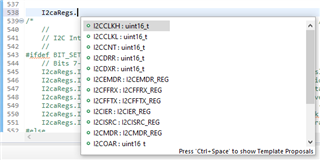
When I enter code to write to a register, CCS identifies the various elements of that register that I may choose from a list to autofill:
Questions:
1. Is this issue due to combining Bitfiled example code with Driverlib code?
2. Am I missing some includes?
3. What is the proper way to write to the registers to set their values?
Thanks,
robin

