This thread has been locked.

If you have a related question, please click the "Ask a related question" button in the top right corner. The newly created question will be automatically linked to this question.

TMS320F28377D: Confusion about continuous sampling example in C2000ware

Part Number: TMS320F28377D
Other Parts Discussed in Thread: C2000WARE

Hello,
 The below code is given in the C2000Ware example for continuous ADC sampling: 

    //
    // Setup the ADC for continuous conversions on channel 0
    //
    setupADCContinuous(ADCA_BASE, 0U);

    //
    // Initialize results buffer
    //
    for(resultsIndex = 0; resultsIndex < RESULTS_BUFFER_SIZE; resultsIndex++)
    {
        adcAResults[resultsIndex] = 0;
    }
    resultsIndex = 0;

    //
    // Enable global Interrupts and higher priority real-time debug events:
    //
    EINT;  // Enable Global interrupt INTM
    ERTM;  // Enable Global realtime interrupt DBGM

    //
    // Take conversions indefinitely in loop
    //
    do
    {
        //
        // Enable ADC interrupts
        //
        ADC_enableInterrupt(ADCA_BASE, ADC_INT_NUMBER1);
        ADC_enableInterrupt(ADCA_BASE, ADC_INT_NUMBER2);
        ADC_enableInterrupt(ADCA_BASE, ADC_INT_NUMBER3);
        ADC_enableInterrupt(ADCA_BASE, ADC_INT_NUMBER4);

        //
        // Clear all interrupts flags(INT1-4)
        //
        HWREGH(ADCA_BASE + ADC_O_INTFLGCLR) = 0x000F;

        //
        // Initialize results index
        //
        resultsIndex = 0;

        //
        // Software force start SOC0 to SOC7
        //
        HWREGH(ADCA_BASE + ADC_O_SOCFRC1) = 0x00FF;

        //
        // Keep taking samples until the results buffer is full
        //
        while(resultsIndex < RESULTS_BUFFER_SIZE)
        {
            //
            // Wait for first set of 8 conversions to complete
            //
            while(false == ADC_getInterruptStatus(ADCA_BASE, ADC_INT_NUMBER3));

            //
            // Clear the interrupt flag
            //
            ADC_clearInterruptStatus(ADCA_BASE, ADC_INT_NUMBER3);

            //
            // Save results for first 8 conversions
            //
            // Note that during this time, the second 8 conversions have
            // already been triggered by EOC6->ADCIN1 and will be actively
            // converting while first 8 results are being saved
            //
            adcAResults[resultsIndex++] = ADC_readResult(ADCARESULT_BASE,
                                                         ADC_SOC_NUMBER0);
            adcAResults[resultsIndex++] = ADC_readResult(ADCARESULT_BASE,
                                                         ADC_SOC_NUMBER1);
            adcAResults[resultsIndex++] = ADC_readResult(ADCARESULT_BASE,
                                                         ADC_SOC_NUMBER2);
            adcAResults[resultsIndex++] = ADC_readResult(ADCARESULT_BASE,
                                                         ADC_SOC_NUMBER3);
            adcAResults[resultsIndex++] = ADC_readResult(ADCARESULT_BASE,
                                                         ADC_SOC_NUMBER4);
            adcAResults[resultsIndex++] = ADC_readResult(ADCARESULT_BASE,
                                                         ADC_SOC_NUMBER5);
            adcAResults[resultsIndex++] = ADC_readResult(ADCARESULT_BASE,
                                                         ADC_SOC_NUMBER6);
            adcAResults[resultsIndex++] = ADC_readResult(ADCARESULT_BASE,
                                                         ADC_SOC_NUMBER7);

            //
            // Wait for the second set of 8 conversions to complete
            //
            while(false == ADC_getInterruptStatus(ADCA_BASE, ADC_INT_NUMBER4));

            //
            // Clear the interrupt flag
            //
            ADC_clearInterruptStatus(ADCA_BASE, ADC_INT_NUMBER4);

            //
            // Save results for second 8 conversions
            //
            // Note that during this time, the first 8 conversions have
            // already been triggered by EOC14->ADCIN2 and will be actively
            // converting while second 8 results are being saved
            //
            adcAResults[resultsIndex++] = ADC_readResult(ADCARESULT_BASE,
                                                         ADC_SOC_NUMBER8);
            adcAResults[resultsIndex++] = ADC_readResult(ADCARESULT_BASE,
                                                         ADC_SOC_NUMBER9);
            adcAResults[resultsIndex++] = ADC_readResult(ADCARESULT_BASE,
                                                         ADC_SOC_NUMBER10);
            adcAResults[resultsIndex++] = ADC_readResult(ADCARESULT_BASE,
                                                         ADC_SOC_NUMBER11);
            adcAResults[resultsIndex++] = ADC_readResult(ADCARESULT_BASE,
                                                         ADC_SOC_NUMBER12);
            adcAResults[resultsIndex++] = ADC_readResult(ADCARESULT_BASE,
                                                         ADC_SOC_NUMBER13);
            adcAResults[resultsIndex++] = ADC_readResult(ADCARESULT_BASE,
                                                         ADC_SOC_NUMBER14);
            adcAResults[resultsIndex++] = ADC_readResult(ADCARESULT_BASE,
                                                         ADC_SOC_NUMBER15);
        }

        //
        // Disable all ADCINT flags to stop sampling
        //
        ADC_disableInterrupt(ADCA_BASE, ADC_INT_NUMBER1);
        ADC_disableInterrupt(ADCA_BASE, ADC_INT_NUMBER2);
        ADC_disableInterrupt(ADCA_BASE, ADC_INT_NUMBER3);
        ADC_disableInterrupt(ADCA_BASE, ADC_INT_NUMBER4);

        //
        // At this point, adcAResults[] contains a sequence of conversions
        // from the selected channel
        //

        //
        // Software breakpoint, hit run again to get updated conversions
        //
        asm("   ESTOP0");
    }

I have a couple of questions regarding the code. First of all, is this code just required upon start-up, and then the continuous sampling begins after the last EOC is generated to trigger the first set of 8 conversions to be made again? It seems that the benefit of continuous sampling is that it can be performed in the background of the CPU, but this code shows that the CPU has to do a lot of waiting until the arrays are filled with samples, which seems to defeat the purpose.

What happens if an interrupt is received by the CPU while these measurements are being taken? Does it jump to that interrupt and return to the continuous sampling once the ISR has been serviced? What if the ISR requires the array to be filled with results, for example if the array is used within the control law accelerator to implement a PID controller?

Since the array is so large, with 256 elements of 12- or 16-bit values, how would one average them to get say an average current or voltage that can be used within the CLA to implement a control law using the DCL? Adding and averaging the results would probably take some time, and would there be a data type large enough to store the intermediate result before casting to a 12- or 16-bit integer for the controller?

Best regards,
Joel

  • Joel,

    Thanks for reaching out to us on the E2E.

    From an ADC perspective, you are correct on the continuous sampling being self sustaining once the initial 8 SOCs are kicked off and no CPU overhead to keep them going.  For the sake of the example we've just coded a simple routine to grab the ADC results and place them in a buffer, as you noted this is CPU intensive as it uses polling to check for new results as well as being interruptible, etc.

    From a system implementation POV it would be advantageous to use the DMA vs the CPU to grab the ADC results and push them to memory.  The DMA can be set up to trigger off the ADC EOC/Interrupt automatically leaving the C28x CPU/CLA to do other things than just shuffle data around.  There is also a DMA/ADC example in the C2000Ware, so essentially you would be combining aspects of these examples into a single piece of code/project.

    Finally, to you last point, on using the data for something meaningful in a system perspective, it really depends on what the signal coming into the ADC is doing.  If we were sampling a sinusoidal input and wanted to extract frequency components then we would need a buffer that is large enough to capture a few periods of data to get a good output from a FFT function.  In this case the CPU or CLA would get called by the DMA ISR after enough data is stored away, then process it, etc.

    In the case you mention, where we are looking to average out/down the noise in a more static measurement, we likely wouldn't need so many sample to be helpful(and the resultant pain of allocating a bigger integer to hold the summation as you mention). 

    As a rule of thumb for oversampling for every 2^(2*n) samples we take we can gain a one bit of ENOB back in resolution until we hit the THD limitations of the converter.  So a good starting point for oversampling might be to average 4 samples to 1 to get 1 bit back from the noise floor in the system.  If we wanted to get 2 bits back, we would need 16x oversampling and so forth.  Obviously this oversampling comes at the expense of the sample rate/time to sample more data from the system, so that tradeoff would need to be considered.  However, given the relative fast sampling speed(MSPS range) we are capable of vs typical control loop times(100s of kHz range) we likely have enough time to accommodate this.

    So, the example is really focused on showing how to set up continuous/max speed sampling and is not really focused so much on the after sampling aspects that you have brought up in your question.  Keep in mind that the ePWM can also trigger the ADC at a consistent rate, but nowhere near the max sample rate if that is important to the input being sampled, so this is also the value of the example.

    Best,

    Matthew 

  • Hi Matthew, 

    Thank you very much for this brilliant response, it definitely answered all my questions. 

    However, regarding the DMA, I was under the impression that we needed to assign some memory to it in the same way if we wanted to implement say IPC communications. In the example available on the C2000Ware I do not see anywhere where we assign memory to the DMA - I just see the following:

    #pragma DATA_SECTION(adcADataBuffer, "ramgs0");
    #pragma DATA_SECTION(adcDDataBuffer, "ramgs0");
    uint16_t adcADataBuffer[RESULTS_BUFFER_SIZE];
    uint16_t adcDDataBuffer[RESULTS_BUFFER_SIZE];

    But that just seems to be assigning memory in the RAM for the data buffers and nothing regarding the DMA. Is it true that we can use the DMA "as is" and don't need to assign any additional memory in the map, and the functions for the DMA is all that we need?

    I will spend today becoming familiar with the DMA on the DSP and see if I can get something working before possibly starting a new thread. So far, I have gathered the following from the example code:

    First ADCA conversion is triggered by a PWM module
    End of conversion triggers the DMA
    End of DMA transfer triggers the ADCA conversion again, and so on

    But you have to have some code that then disables the PWM interrupt, such that it cannot again trigger an ADC conversion and only the DMA is responsible for causing another ADC conversion from that point onward. There is obviously a lot more to the code but this is probably the important part that I have managed to grasp.

    The part I find difficult is actually how we are storing and how to manipulate the data. This example again seems to have a buffer of results that are stored in the DMA - but they are stored result by result avoiding the CPU needing to keep filling the array. Is there a way to check the array is full, or would one just have some kind of counter that is equal to the buffer size, so that we can then average the results together to get a final result we can use in the DCL control law? It seems like, since the DMA doesn't have any mathematical abilities, we still will need a rather large data type to accommodate say 32, 16-bit samples added together. My control bandwidth is 80-100kHz, and with the suggested 320nS acquisition time for the differential measurement, 32 is probably the largest multiple of 16 I can accommodate. You mentioned that it will be a combination of the two programs, but neither really seem to do anything with the data once it is stored to give an indication of how best to actually use the results of the program. 

    UPDATE: After spending today becoming familiar with the DMA, I have managed to mostly get the code working. It seems though that the code only fills the buffer and transfers the data once. The following function executes only once: 

    // dmach1ISR - This is called at the end of the DMA transfer, the conversions are stopped by removing the first SOC from the last.
    #pragma CODE_SECTION(dmach1ISR, ".TI.ramfunc");
    __interrupt void dmach1ISR(void)
    {
        debug2++;   // Debugger check ISR
    
        // Stop the ADC by removing the trigger for SOC0
        ADC_setInterruptSOCTrigger(ADCA_BASE, ADC_SOC_NUMBER0,
                                   ADC_INT_SOC_TRIGGER_NONE);
        ADC_setInterruptSOCTrigger(ADCD_BASE, ADC_SOC_NUMBER0,
                                   ADC_INT_SOC_TRIGGER_NONE);
    
        // Acknowledge interrupt
        Interrupt_clearACKGroup(INTERRUPT_ACK_GROUP7);
    }

    Which seems to remove the ADC trigger and therefore performs only one set of transfers and then terminates the example. The function that removes the ePWM trigger makes sense, since we only want it to be triggered by the SOCA of an EPWM for the first cycle, it should then be self sustaining using the ADCINT and the DMA INTs. 

    Would it simply be a case of removing this function to allow continuous ADC transfers with the DMA? Or is there more to it than that? Thanks in advance!

    Best regards,

    Joel

  • Joel,

    The #pragma is how we direct the code to place a variable(in this case the DMA buffers) to a specific memory location.  This allows us to pass this address to the DMA so we know that it will be consistent and no other code/data will over-write it, etc.  You will see in the .cmd file that ramgs0 is defined there.

    For completely continuous ADC conversions, you can remove the code you have mentioned.  In this case you may want to set up 2 buffers for each ADC that is converting so you can have a "ping/pong" type implementation, the reason being so that you don't have any timing concerns on using the data in the buffer before the DMA over-writes it with new ADC data.

    Something like

    ADCResults 0-63 ->ADCBuf1

    when ADCBuf1 is full, trigger the DMA ISR to let the CPU or CLA process the data

    You can preload the DMA shadow beginning address to contain the start address of ADCBuf2 for the next transfer so ADCBuf1 is not over-written

    Part of the action of the DMA ISR would be to set the shadow beginning address back to ADCBuf1 origin so for the 3rd transfer we go back to the ADCBuf1, while you process ADCBuf2, etc.

    The DMA also has a CONT bit, that you will want to set to keep it running independent of the ISRs, etc.

    Best,

    Matthew

  • Hi Matthew,

    Again, a very helpful response so thank you. In my C2000Ware the ADC examples, including the continuous ADC with DMA example, do not have any command files with them therefore my confusion was due to the fact I could not see the definitions. Is there a directory for this file, or can you send the file here, because as I mentioned it does not seem to be in a folder with the ADC codes.

    I actually only need one ADC to have continuous conversions - my other signals are not as critical and can be sampled just a few times the switching frequency, I planned to just use some other form of sampling for those that doesn't require as much difficulty. In this case, I suppose I would not need any ping-ponging? Or would that still be required so that the DMA is being filled again once the DMA INT has been sent and the CPU starts processing the data to hand it over to the controller in the CLA?

    Regarding setting the shadow beginning address back to the address of ADCbuf1, would you still need to do that even if we are using a single ADC buffer of say 32, 16-bit words? I feel like that makes sense, because the DMA needs to be reset back to the start of where it was reading data, to start reading data again from the same buffer. 

    Thanks for the tip on CONT. If we are only using one ADC buffer, do we still need to let the DMA know within it's ISR to jump back to the start of the ADC buffer that has just been oversampled and transferred with the DMA? If so, do we just get the start of the buffer address from the debugger and place it in the SRC_BEG_ADDR_SHADOW Register field? Or is it slightly more complicated? I set continuous mode and didn't tell the DMA explicitly to loop back to the start of the ADC buffer but it seems to be doing that itself anyway.

    Just a quick one: in the function here, we specify that channel 0 of ADCA is to be converted.

    ADC_setupSOC(adcBase, ADC_SOC_NUMBER0, ADC_TRIGGER_EPWM1_SOCA,
                         (ADC_Channel)channel, acqps_fine);
                         
                         setupADCContinuous(ADCA_BASE, 0);

    Finally, in the code given by TI, the configuration sets up the mode as:

        DMA_configMode(DMA_CH1_BASE, DMA_TRIGGER_ADCA2,
                       (DMA_CFG_ONESHOT_DISABLE | DMA_CFG_CONTINUOUS_ENABLE |
                        DMA_CFG_SIZE_32BIT));

    CFG_SIZE as 32-bit. Why is this, if we are only transferring 12-bit pieces of data? In my case it is 16-bit, but then you'd expect this field to be 16-bit configuration and not 32-bit. Note I changed the CONT bit in this function. 

    Sorry for all the questions but I feel I am very close to getting this code to work. I like to understand exactly what is happening so that I can debug it properly down the line!


    Best regards,

    Joel

  • Joel,

    Matt is out of office today. He will return to office on Monday, so please expect response by Monday/Tuesday.

    Thanks & Regards,

    Santosh

  • Hi Matthew,

    Just coming back to this suggestion as I am attempting now to code the program for ping-ponging between buffers as I do now need to do continuous conversions on ADCB and ADCD. ADCD is 16-bit, whereas ADCB is 12-bit measurements. Should the settings be the same for the data transfer?

    To ping-pong effectively it seems that you need to set the shadow register for the DMAs to convert - both DMA1 and DMA channel 2. I suppose this would then require interrupts to be enabled and used for both DMA channels, with the shadow address being set to the Buffer 1 in DMA INT2 and Buffer 2 in DMA INT 1? Does this seem correct? 

    Best,

    Joel

  • Also in the continuous DMA example, when setting up ADCA and ADCD, the following code exists: 

    void configureDMAChannels(void)
    {
        //
        // DMA channel 1 set up for ADCA
        //
        DMA_configAddresses(DMA_CH1_BASE, (uint16_t *)&adcADataBuffer,
                            (uint16_t *)ADCARESULT_BASE);
    
        //
        // Perform enough 16-word bursts to fill the results buffer. Data will be
        // transferred 32 bits at a time hence the address steps below.
        //
        DMA_configBurst(DMA_CH1_BASE, 16, 2, 2);
        DMA_configTransfer(DMA_CH1_BASE, (RESULTS_BUFFER_SIZE >> 4), -14, 2);
        DMA_configMode(DMA_CH1_BASE, DMA_TRIGGER_ADCA2,
                       (DMA_CFG_ONESHOT_DISABLE | DMA_CFG_CONTINUOUS_DISABLE |
                        DMA_CFG_SIZE_32BIT));
    
        DMA_enableTrigger(DMA_CH1_BASE);
        DMA_disableOverrunInterrupt(DMA_CH1_BASE);
        DMA_setInterruptMode(DMA_CH1_BASE, DMA_INT_AT_END);
        DMA_enableInterrupt(DMA_CH1_BASE);
    
        //
        // DMA channel 2 set up for ADCD
        //
        DMA_configAddresses(DMA_CH2_BASE, (uint16_t *)&adcDDataBuffer,
                            (uint16_t *)ADCBRESULT_BASE);
    
        //
        // Perform enough 16-word bursts to fill the results buffer. Data will be
        // transferred 32 bits at a time hence the address steps below.
        //
        DMA_configBurst(DMA_CH2_BASE, 16, 2, 2);
        DMA_configTransfer(DMA_CH2_BASE, (RESULTS_BUFFER_SIZE >> 4), -14, 2);
        DMA_configMode(DMA_CH2_BASE, DMA_TRIGGER_ADCA2,
                       (DMA_CFG_ONESHOT_DISABLE | DMA_CFG_CONTINUOUS_DISABLE |
                        DMA_CFG_SIZE_32BIT));
    
        DMA_enableTrigger(DMA_CH2_BASE);
        DMA_disableOverrunInterrupt(DMA_CH2_BASE);
        DMA_setInterruptMode(DMA_CH2_BASE, DMA_INT_AT_END);
        DMA_enableInterrupt(DMA_CH2_BASE);
    }

    Why when setting up ADCD does the code set  (uint16_t *)ADCBRESULT_BASE as the argument for the ADC result base? Surely this should be ADCDRESULT_BASE? Is that a mistake or something I am missing?

    Best regards,

    Joel

  • Furthermore, if you could just clarify regarding why the data length for transfers is set to 32-bits, despite only ever transmitting 16-bit words in the DMA. Would it not be faster/more efficient to set this to 16-bit transfers, since the leftmost 16-bits won't actually contain any information that is useful.

    Finally, could you help me with the setting of the shadow registers for changing the address to be sent to the DMA. I cannot find this information in the DMA API guide DMA Module — F2837xd API Guide (ti.com)

    At the moment my two DMA channels are just sampling the same buffer because I am not changing the address during the DMA ISRs. I assume I will need two DMA ISR's:

    DMA1 triggered by the ADCD INT, set DMA INT once array filled, and set shadow address (not sure how to do that, yet)

    Then, we should have a second DMA INT, for the second array. I assumed that this would be triggered by an INT on whichever ADC it is converting, for example ADCB. However, do we not need to wait for DMA1 to finish first according to the above pseudocode - but I do not see anywhere that DMA2 could be triggered by the end of DMA1. 

    My question therefore, alongside the channel transfer length one, is how do we set up the interrupts to ensure that only one buffer is being filled while the other is being processed while ensuring no overwriting - it seems that you cannot do this in parallel and some level of waiting will be involved which will also reduce the effective achievable sampling rate of the ADC's, or alternatively how large the array that holds the values can be. Is it true that you cannot fill DMA channel 1 and DMA channel 2 simultaneously? If so, there must be some code in DMA INT2 that checks whether the first DMA has finished first?

    Maybe the following is in important note, from the TRM: "If implementing a ping-pong buffer scheme with continuous mode of operation, then the interrupt would be generated at the beginning, just after the working registers are copied to the shadow set. If the DMA does not operate in continuous mode, then the interrupt is typically generated at the end when the transfer is complete." I currently have it set up to INT at end of the DMA transfer, so might be one reason why it is not working as expected.

    It seems to me that, in the example, we are just filling two arrays with values. There is no communication between the two channels. For ping-pong operation, the two DMA ISR's should call the driverlib function DMA_configAddresses(uint32_t base, const void *destAddr, const void *srcAddr); every time, to reconfigure the addresses for where the DMA should start reading data, and where it should save it to. Setting for example destAddr to ADCBuf2 in the first DMA ISR, and destAddr to ADCBuf1 in the second DMA ISR. The source address with be the ADC base that holds the results that we want to store in the respective buffer. Does this sound like the right method? 


    Hope that makes sense, and I look forward to your reply.

    Best regards,

    Joel

  • Joel,

    I'm a bit behind in replying here, there's some more details I need to investigate before I reply.  I should reply by the end of day today worst case.  Appreciate your patience.

    Best,

    Matthew

  • Hi Matthew, 

    No problem, I understand there is a lot to reply to. Just as an update, I changed the code so that ADCDbuff is now filled with differential values, and ADCBbuff is filled with single-ended values. This was done by fixing that part of the code where, for some reason, the TI code was filling the second DMA channel, with ADCD as the destination, with data from ADCB source rather than ADCD:

    DMA_configAddresses(DMA_CH2_BASE, (uint16_t *)&adcDDataBuffer,
    (uint16_t *)ADCBRESULT_BASE);

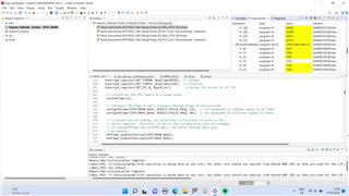
    Here is the new screenshot: 

    However I am still not sure this is fully correct, as I have not set any shadow addresses within the two DMA ISR's that I have setup. So this code, as it stands, just fills DMA channel 2 with data from a 12-bit ADC channel continuously, and DMA channel 1 fills with data from a 16-bit ADC channel continuously. It seems to work OK but I would like to get the benefits of setting up a ping-pong between them such that I can more effectively actually process this data.

    Take your time. 

    Best,
    Joel

  • Joel,

    I'm going to address the DMA aspects/ping pong aspects first. A colleague pointed out to me that we have an example of a ping/pong buffer with ADC as part of the C2000 Academy, with code showing how to change the shadow in the correct order in the same ISR here.  https://dev.ti.com/tirex/explore/node?node=AW0glYTcKnM5i4HMCOUt.Q__jEBbtmC__LATEST

    You are correct that the comments and the ADCxRESULTBASE are not consistent, understand that you have resolved this already , but wanted to confirm.

    In terms of the 32-bit data size, I think this is being done for efficiency sake it will take advantage of the 32-bit bus width of the C2000 CPU.  Even with only 12-bit data, the DMA will transfer a full 16-bit word to memory each time, so there's no other efficiencies in play here.  The other thing to point out is that even though the data size is set to 32-bit the DMA increments/decrements still use 16-bit words as the baseline.  I think you've already figured that out or understood it, but wanted to be sure.

    In terms of the linker/cmd not being directly visible in the project, it is being referenced in the project settings (right click on the project and select properties) and look at the linker section.  You should be able to find the path of the file.  I think you should be able to expand the "includes" in the project tree to see the dir path to the folder as well.

    For your last question, I think you can expand on the example above, and set a ping/pong for each ADC independently.  For best throughput the buffers all need to be in physically different RAM blocks, LSx or GSx etc.  Reason for this is that if the buffer is split inside a RAM block the CPU read will stall the DMA write when they occur at the same time(which was the whole reason for the ping/pong style approach).

    I'm sure I've missed something in the above :) please let me know if there are additional points you need clarity on.

    Best,

    Matthew

  • Hi Matthew

    Getting there slowly. Although I am getting some errors when implementing the code in the example above. I coded the below using a combination of the code you have given and the original DMA example in the C2000Ware:

    // dmach1ISR - Flyback Voltage Ping-Pong Buffer on ADCD
    #pragma CODE_SECTION(dmach1ISR, ".TI.ramfunc");
    __interrupt void dmach1ISR(void)
    {
        // Acknowledge interrupt
        Interrupt_clearACKGroup(INTERRUPT_ACK_GROUP7);
    
        dma1Count++;
        accumulator_voltage = 0;
        data_voltage = 0;
        average_voltage = 0;
        voltage_cast = 0;
    
        uint16_t *adcDBufPtr;    // Pointer to interchange between ping and pong buffers for reading/writing
        uint16_t i;
    
        if(PingPongDState == 0) {
            // Set DMA address to the start at ping buffer
            DMA_configAddresses(DMA_CH1_BASE,
                                (const void *)adcDDataBuffer,
                                (const void *)ADCDRESULT_BASE);
    
            // Fill the buffer with contents from the pong buffer
            adcDBufPtr = adcDDataBuffer + RESULTS_BUFFER_SIZE;
            for(i = 0; i < RESULTS_BUFFER_SIZE; i++) {
               data_voltage = adcDDataBuffer[i];
               accumulator_voltage += data_voltage;
            }
        }
    
        else {
            // Set DMA address to start at pong buffer
            DMA_configAddresses(DMA_CH1_BASE,
                                (const void *)adcDDataBuffer + RESULTS_BUFFER_SIZE,
                                (const void *)ADCDRESULT_BASE);
            // Fill the buffer with contents from the pong buffer
                   adcDBufPtr = adcDDataBuffer;
                   for(i = 0; i < RESULTS_BUFFER_SIZE; i++) {
                      data_voltage = adcDDataBuffer[i];
                      accumulator_voltage += data_voltage;
                   }
        }
    
        PingPongDState ^= 1;
    
        average_voltage = (accumulator_voltage / 0x20);   // 32-bit average of 32 16-bit results for voltage
        voltage_cast = (uint16_t)(average_voltage); // Cast to 16-bit value
    }
    
    #pragma CODE_SECTION(dmach2ISR, ".TI.ramfunc");
    __interrupt void dmach2ISR(void)
    {
        // Acknowledge interrupt
        Interrupt_clearACKGroup(INTERRUPT_ACK_GROUP7);
    
        dma2Count++;
    
        // Reset all values before filling any buffers
        accumulator_current = 0;
        data_current = 0;
        average_current = 0;
        current_cast = 0;
    
        uint16_t *adcBBufPtr;     // Pointer to interchange between ping and pong buffers for reading/writing
        uint16_t j;
    
        if(PingPongBState == 0) {
            // Set DMA address to the start at ping buffer
            DMA_configAddresses(DMA_CH2_BASE,
                                (const void *)adcBDataBuffer,
                                (const void *)ADCBRESULT_BASE);
    
            // Fill the buffer with contents from the pong buffer
            adcBBufPtr = adcBDataBuffer + RESULTS_BUFFER_SIZE;
            for(j = 0; j < RESULTS_BUFFER_SIZE; j++) {
               data_current = adcBDataBuffer[j];
               accumulator_current += data_current;
            }
        }
    
        else {
            // Set DMA address to start at pong buffer
            DMA_configAddresses(DMA_CH2_BASE,
                                (const void *)adcBDataBuffer + RESULTS_BUFFER_SIZE,
                                (const void *)ADCBRESULT_BASE);
            // Fill the buffer with contents from the pong buffer
                   adcBBufPtr = adcBDataBuffer;
                   for(j = 0; j < RESULTS_BUFFER_SIZE; j++) {
                      data_current = adcBDataBuffer[j];
                      accumulator_current += data_current;
                   }
        }
    
        PingPongBState ^= 1;
    
        average_current = (accumulator_current / 0x20);   // 32-bit average of 32 16-bit results for current
        current_cast = (uint16_t)(average_current);
    }

    With the following DMA set up, again very similar to the example you given me but slightly different, as I kept the ADCD/ADCB_RESULT_BASE the same: 

    void configureDMAChannels(void)
    {
        // DMA channel 1 set up for ADCD
        // Set up ADCD which has differential amplifier for 16-bit measurements
        DMA_configAddresses(DMA_CH1_BASE, (const void *)&adcDDataBuffer,
                            (const void *)ADCDRESULT_BASE);
    
        // Perform enough 16-word bursts to fill the results buffer. Data will be
        // transferred 32 bits at a time hence the address steps below.
        DMA_configBurst(DMA_CH1_BASE, 1, 0, 0);
        DMA_configTransfer(DMA_CH1_BASE, RESULTS_BUFFER_SIZE, 0, 1);
        DMA_configMode(DMA_CH1_BASE, DMA_TRIGGER_ADCD2,
                       (DMA_CFG_ONESHOT_DISABLE | DMA_CFG_CONTINUOUS_ENABLE |
                        DMA_CFG_SIZE_16BIT));
    
        DMA_enableTrigger(DMA_CH1_BASE);
        DMA_disableOverrunInterrupt(DMA_CH1_BASE);
        DMA_setInterruptMode(DMA_CH1_BASE, DMA_INT_AT_BEGINNING);
        DMA_enableInterrupt(DMA_CH1_BASE);
    
        // DMA channel 2 set up for ADCB
        DMA_configAddresses(DMA_CH2_BASE, (const void *)&adcBDataBuffer,
                                (const void *)ADCBRESULT_BASE);
    
        // Perform enough 16-word bursts to fill the results buffer. Data will be
        // transferred 32 bits at a time hence the address steps below.
        DMA_configBurst(DMA_CH2_BASE, 1, 0, 0);
        DMA_configTransfer(DMA_CH2_BASE, RESULTS_BUFFER_SIZE, 0, 1);
        DMA_configMode(DMA_CH2_BASE, DMA_TRIGGER_ADCB2,
                      (DMA_CFG_ONESHOT_DISABLE | DMA_CFG_CONTINUOUS_ENABLE |
                       DMA_CFG_SIZE_16BIT));
    
        DMA_enableTrigger(DMA_CH2_BASE);
        DMA_disableOverrunInterrupt(DMA_CH2_BASE);
        DMA_setInterruptMode(DMA_CH2_BASE, DMA_INT_AT_BEGINNING);
        DMA_enableInterrupt(DMA_CH2_BASE);
    }

    Because I changed the pointers to const void * instead of INT16_T as they originally were, I get the new warnings below:

    "../MPM_CPU1.c", line 465: warning #1219-D: arithmetic on pointer to void or function type
    "../MPM_CPU1.c", line 445: warning #552-D: variable "adcDBufPtr" was set but never used
    "../MPM_CPU1.c", line 515: warning #1219-D: arithmetic on pointer to void or function type
    "../MPM_CPU1.c", line 495: warning #552-D: variable "adcBBufPtr" was set but never used

    But the lines of code I have inserted are carbon copied from the DMA example you have given me. I am unsure if the line 

     adcDBufPtr = adcDDataBuffer + RESULTS_BUFFER_SIZE;

    Should be

     *adcDBufPtr = adcDDataBuffer + RESULTS_BUFFER_SIZE;

    But that would not then explain the "arithmetic on pointer to void or function type". Again, the example code performs the same arithmetic on the same pointer of the same type - so this warning is very strange! It still compiles however, maybe this is an expected error? If so, and the code above just missing a * before the pointer command, then maybe I could see if I get the results I expect.

    Let me know your thoughts?

    Best,
    Joel

  • Joel,

    I'm out of the office for the next couple of days returning on Monday the 23rd.  I'll try to take a look and reply tommorow before I head out, but worse case will give a reply by Monday EOB.

    Best,

    Matthew

  • Hi Matthew,

    Hope you had a good weekend by the time you have read this reply. Just to let you know that with the errors above the code somehow still manages to run, I think as expected... However I have been trying today to go over the DMA code and have now included the timer code in the example you gave me previously. Even though the timer is set to check if the ISR takes longer than 1ms, the counter is incrementing every ISR to indicate that the buffers are being overwritten. 

    I think there must be something wrong with my initialization, but I am copying everything from the example. My signals are set up for continuous ADC conversions, a sawtooth wave current of around 1MHz and a DC output voltage. I wanted to set up the DMA with continuous sampling because I was led to believe this was the fastest way to measure and average a high speed signal at the maximum frequency the ADC can handle. 

    However, as I mentioned above the ISR is taking longer than 1ms, which would indicate even that the code given wouldn't be suitable for an AC signal with a frequency of 1MHz because the DMA ISR's are taking such a long time to execute, meaning that the contents of the buffer are overwritten very easily. The example does say to increase the buffer size/increase the acquisition period, but it seems like doing that will still have very limited benefits considering the very slow ISR loop within the DMA.

    My question is, how fast can a DMA actually transfer data? The data sheet says 4 cycles/word, so it would take 128 clock cycles to fill a 32 element array of 16-bit integers, which is around 640nS. 

    At 20nS per word, this is less than the acquisiton period for a 12-bit and certainly a 16-bit integer value, so the limiting factor for the speed of filling the array will be the AQCPS and it is likely the array might be filled with duplicate values if the acquisition period exceeds 20ns. 

    It really does not make sense, then, that for a worst-case 1us time taken to fill a 32 element array of 16-bit integer values, that the DMA code and any averaging done would take 999uS or longer, assuming the counter is incremented if the timer ISR has a time greater than 1mS. 

    When you get time tomorrow please do try and clear up these issues regarding the throughput of the DMA and give any ideas for why the ISR may be taking so long. If 1ms is a standard time for a DMA transfer ISR, then that is OK, but I will need to find an alternative way to sample and process my data because that's not good enough for a 1MHz AC signal!

    Enjoy the rest of your weekend,
    Joel

  • Joel,

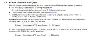
    Thanks for the additional detail.  Based on my interpretation of the TRM the datarate of the DMA should be slightly faster than you mention at 3 cycles/word given from the TRM below.

    If I assume worst case 16-bit transfers this should be:

    32 16-bit words, in 4 bursts of 8 words each time:

    4 bursts*(3cycles/word)*8 words/burst)+1) = 100 cycles @ 5ns = 500ns for 32 ADC results.

    If we picked 32-bit word length, we could knock this down to ~250ns.

    All this to say I agree that 1ms time is not what I would expect either, even with the overhead of flushing the pipeline/etc.

    A few things to consider:

    1)Code location for the ISR, is it in flash vs RAM.  Keep in mind that flash will be running at 3WS at 200MHz ~50MHz, basically 4 cycles to fetch instructions in flash vs 1 cycle in RAM

    2)If you are using the same RAM for both sets of the ping/pong buffer, then we could get contention and this would add a cycle of delay for each side(the DMA and the CPU depending on which made the request).  That might be moot if the time between samples is bigger than 500ns, but I don't think this is true.  This may be where you are getting the 4 cycles a word from above, but as you have shown this is still only 640ns, which assumes we stall on every word.

    3)If your code is is in the same RAM block as the DMA buffer, but I doubt this is the case.

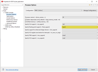
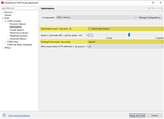
    4)Optimization: both code generation as well as using the floating point accelerator:

    Right click on the project and select "properties" at the bottom of the drop down.

    Then make sure the processor options as well as optimization are configured as shown below, with both FPU32 selected, as well as opt level 2 and floating point mode set to relaxed.  This should give the best performance

    If you are still seeing very slow ISR performance, we may need to profile the code to see exactly what is going on. 

    Alternatively since you are taking a 2^n power of samples, we could take advantage of this and just use a simple summation and bitwise shift(by 5) of the samples to get the average.  Since the ADC doesn't provide sub bit resolution, this should give a reasonably accurate result without involving alot of FP math, etc.

    Let me know what you think on the above.

    Best,

    Matthew

  • Hi Matthew,

    Lots to work on here - will have a go rest of the week/weekend and get back to you with any issues. 
    I really appreciate the help so far. 

    Best, 
    Joel