This thread has been locked.

If you have a related question, please click the "Ask a related question" button in the top right corner. The newly created question will be automatically linked to this question.

TMDSHVMTRINSPIN: Controlling starting current of the motor

Part Number: TMDSHVMTRINSPIN
Other Parts Discussed in Thread: C2000WARE, C2000WARE-MOTORCONTROL-SDK

Hi team,

https://e2e.ti.com/support/microcontrollers/c2000-microcontrollers-group/c2000/f/c2000-microcontrollers-forum/1081923/tmdshvmtrinspin-starting-jerk

Above link is my previous thread please check it once.

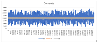
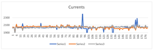
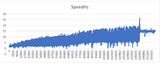
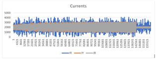
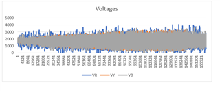
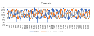
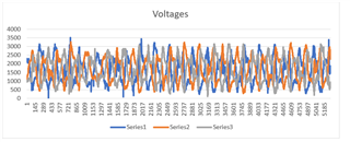
How we can control the starting current of the motor, because of this high starting current our motor windings were burned.

My motor did big noise at the starting.

Can anyone help me to solve this issue?


Below are my motor parameters 

#if (USER_MOTOR == Estun_EMJ_04APB22_A)
#define USER_MOTOR_TYPE MOTOR_TYPE_PM
#define USER_MOTOR_NUM_POLE_PAIRS (20)
#define USER_MOTOR_Rr_Ohm (0.0)
#define USER_MOTOR_Rs_Ohm (2.25093718)
#define USER_MOTOR_Ls_d_H (0.033496008015)
#define USER_MOTOR_Ls_q_H (0.033496008015)
#define USER_MOTOR_RATED_FLUX_VpHz (4.8)
#define USER_MOTOR_MAGNETIZING_CURRENT_A (NULL)
#define USER_MOTOR_RES_EST_CURRENT_A (1.5)
#define USER_MOTOR_IND_EST_CURRENT_A (-1.5)
#define USER_MOTOR_MAX_CURRENT_A (15.0)
#define USER_MOTOR_FLUX_EXC_FREQ_Hz (20.0)
#define USER_MOTOR_NUM_ENC_SLOTS (2500.0)
#define USER_MOTOR_INERTIA_Kgm2 (3.10002e-02)

#define USER_MOTOR_FREQ_MIN_HZ (5.0) // Hz
#define USER_MOTOR_FREQ_MAX_HZ (48.0) // Hz 120%of rated //increased to 48 from 30
#define USER_MOTOR_FREQ_LOW_HZ (4.0) // Hz //increased to 4 from 2.5
#define USER_MOTOR_FREQ_HIGH_HZ (40.0) // Hz //increased to 40 ffrom 25
#define USER_MOTOR_VOLT_MIN_V (45.0) // Volt
#define USER_MOTOR_VOLT_MAX_V (300.0) // Volt

  • Having an incorrect Rs value (especially a value higher than the actual Rs) will make the start-up behave poorly. You might refer to chapter 14 "Managing Full Load at Startup, Low-Speed and Speed Reversal" in InstaSPIN-FOC and InstaSPIN-MOTION User's Guide

    https://www.ti.com/lit/spruhj1

    1. Enable stator Rs recalibration before startup
    2. Enable forced angle
    3. Make sure that the current ADC offset is calibrated.
  • Oddly PM fails to send typed message error dialog states to contact administrator.

    Hi DS,

    Perhaps set the user.h speed Pi MAX sat current (15A) much lower or just above EST 1.5A, but 1.5A seems to low. I set both EST 5.0A/-4.5A(-10%) respectively for my motor and MAX (speed PI saturation) to 5.6A where current remains stable.

    Perhaps you can update speed Pi MAX saturation EST to higher values, say EST 2.5A Pi MAX sat (3.5A) just to get rotor rolling with load. Then at certain speed Hz >15Hz, slowly update speed Pi MAX current up to 15A inside main_ISR while loop, prior to SV_run() and after online=true. Likewise after stopping motor set EST/MAX variables back, e.g. 2.5A/3.5A inside the main ISR while loop Online=false. 

    Seemingly on startup speed Pi rapidly saturates (loaded rotor) MAX (15A) when Bwdelta is greatly increased. That may be due to Ki/Kp speed values used to reduce current oscillations near Pi saturation points. Perhaps when rotor is at very low Hz (<5Hz), a wider BWdelta aperture allows speed Pi to rapidly saturate to MAX 15A. I never set speed Pi MAX higher than where phase current wildly oscillates and stator coils are making pinging noises.

  • Hi Luo

    We have studied and tried with the above conditions, but there is no change in motor stating behavior.

    1.Because of this high stating current our motor windings burned every time. 

  • How much load is adding on the motor when start it? Do you set the USER_MOTOR_MAX_CURRENT_A according to the inverter and motor? You may limit the USER_MOTOR_MAX_CURRENT_A and reduce the maximum acceleration for startup.

    #define USER_MOTOR_MAX_CURRENT_A (15.0)

    Enable the forced angle and try to tune the two parameters below in user.h. You may try to increase the USER_FORCE_ANGLE_FREQ_Hz  a little bit.

    //! \brief Defines the low speed limit for the flux integrator, pu
    //! \brief This is the speed range (CW/CCW) at which the ForceAngle object is active, but only if Enabled
    //! \brief Outside of this speed - or if Disabled - the ForcAngle will NEVER be active and the angle is provided by FAST only
    #define USER_ZEROSPEEDLIMIT (0.5 / USER_IQ_FULL_SCALE_FREQ_Hz) // 0.002 pu, 1-5 Hz typical; Hz = USER_ZEROSPEEDLIMIT * USER_IQ_FULL_SCALE_FREQ_Hz

    //! \brief Defines the force angle frequency, Hz
    //! \brief Frequency of stator vector rotation used by the ForceAngle object
    //! \brief Can be positive or negative
    #define USER_FORCE_ANGLE_FREQ_Hz (2.0 * USER_ZEROSPEEDLIMIT * USER_IQ_FULL_SCALE_FREQ_Hz) // 1.0 Typical force angle start-up speed

  • Hi Luo,

    How much load is adding on the motor when start it?

    We start with full load, it's HVLS fan.

    Do you set the USER_MOTOR_MAX_CURRENT_A according to the inverter and motor?

    Yes we set maximum current correctly according  motor and inverter.

    #define USER_ZEROSPEEDLIMIT

    we couldn't found this parameter in my user.h  (we are using C2000Ware_MotorControl_SDK_3_00_01_00).

    #define USER_FORCE_ANGLE_FREQ_Hz

    we set this to 1Hz

    and we set  #define USER_MAX_ACCEL_Hzps   to 1.

  • We start with full load, it's HVLS fan.

    You may take a look at the Universal Motor Control lab, and refer to this lab to use different maximum current and acceleration for startup. 

    C2000WARE-MOTORCONTROL-SDK: https://www.ti.com/tool/C2000WARE-MOTORCONTROL-SDK

    Universal Project and Lab User’s Guide: https://www.ti.com/lit/ug/spruj26/spruj26.pdf

    Example lab project at the folder: C:\ti\c2000\C2000Ware_MotorControl_SDK_3_03_00_00\solutions\universal_motorcontrol_lab\f28002x

    You may try to capture some current waveforms to post them on this forum that could help us to understand this issue. And it's possible to start and run the motor with a light load to see what happens and capture some waveforms for comparison. 

    It's better to identify the motor parameter for running the motor in the following labs. Or make sure that you set the right motor parameters.

  • Hi Luo,
    I will provide the data,
    Thanks for the support.

  • Please let's know if have any update and further questions, we'd like to close this thread first. Thanks!

  • Hi Luo,

    1. In user.h we set the USER_MAX_ACCEL_Hzps to 0.5 and USER_FORCE_ANGLE_FREQ_Hz  to 1.

    2. in labs.h we set accelerationMax_Hzps to 1.

    3.We tested the PMSM motor (Estun_EMJ_04APB22_A) and we captured the feed back speed from serial port( I have attached image in below)

    4. We give the reference speed(Hz) = 50Hz.

    5.In the above we observed that there is oscillations in the feedback speed.

  • Do you capture any current waveform?

    How do you judge an oscillation in the feedback speed?

    Do you try to identify the motor parameters and tune the gains of the speed PI controller? And check if there is any changes when tune the gains?

  • Hi Luo,

    Thanks for the reply,

    1.We tested our motor in no load and load, I have attached the ADC_Data plots of both cases

    2.Below are my code settings in both load and no-load conditions.

    2a. user.h settings.

    #define USER_MAX_ACCEL_Hzps        ((float32_t)(1.0))

    #define USER_FORCE_ANGLE_FREQ_Hz            ((float32_t)(1.0))

    2b.Motor parameters 

    #if (USER_MOTOR == Estun_EMJ_04APB22_A)

    #define USER_MOTOR_TYPE                    MOTOR_TYPE_PM

    #define USER_MOTOR_NUM_POLE_PAIRS         (20)

    #define USER_MOTOR_Rr_Ohm                 (0.0)

    #define USER_MOTOR_Rs_Ohm                 (2.35093718)

    #define USER_MOTOR_Ls_d_H                 (0.033496008015)

    #define USER_MOTOR_Ls_q_H                 (0.033496008015)

    #define USER_MOTOR_RATED_FLUX_VpHz        (5.5)

    #define USER_MOTOR_MAGNETIZING_CURRENT_A  (NULL)

    #define USER_MOTOR_RES_EST_CURRENT_A      (1.0)

    #define USER_MOTOR_IND_EST_CURRENT_A      (-1.0)

    #define USER_MOTOR_MAX_CURRENT_A          (7.4)

    #define USER_MOTOR_FLUX_EXC_FREQ_Hz       (20.0)

    #define USER_MOTOR_NUM_ENC_SLOTS          (2500.0)

    #define USER_MOTOR_INERTIA_Kgm2           (3.10002e-02)

    #define USER_MOTOR_FREQ_MIN_HZ             (10.0)           // Hz

    #define USER_MOTOR_FREQ_MAX_HZ            (48.0)         // Hz  120%of rated //increased to 48 from 30

    #define USER_MOTOR_FREQ_LOW_HZ            (4.0)          // Hz   //increased to 4 from 2.5

    #define USER_MOTOR_FREQ_HIGH_HZ           (40.0)         // Hz   //increased to 40 ffrom 25

    #define USER_MOTOR_VOLT_MIN_V             (35.0)          // Volt

    #define USER_MOTOR_VOLT_MAX_V             (260.0)         // Volt

    2c. Labs.h settings

    accelerationMax_Hzps   (0.5)

    A. ADC data of speed, current and voltage plots: (No load)


    Zoom in voltages and currents: (No load)

    B. ADC data of speed, current and voltage plots: (Load)

    Zoom in voltages and currents: (Load)

    3. In load condition motor ran with vibrations and did some noise


  • Any voltage and current waveforms captured by an oscilloscope with current probe? And do you try to tune the speed controller?

    I don't think there is any issue from the InstaSPIN-FOC algorithm, you may try to tune the current and speed controller, and the acceleration according to the system.

    BTW, try to identify the motor parameters without any load. Make sure that the motor run smoothly without vibration by tuning the identification variables.

  • It's been a week since we heard from you,  so I am assuming you no longer need clarification for your question that will be marking this thread as closed. You can reply with a post or create a new thread if you have any further question on this topic. Thanks.

  • Hi Luo ,
    Thanks for the reply, Motor ran successfully but there is one jerk at initial stage, How we can remove that?

  • Make sure that the ADC offset is calibrated correctly, enable the force angle, tune the speed PI controller and acceleration for startup.