Part Number: TMS320F28377D
Other Parts Discussed in Thread: C2000WARE, SYSCONFIG
Hi,
I am almost done working on my C2000Ware code for a high voltage DC/DC converter but had a few questions about making the code more safe when I want to stop the code execution.
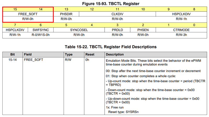
At the moment, when I halt the debugger, the DSP seems to continue outputting signals to the GPIO's, meaning that my PWM is still being outputted. I would like the code such that when the debugger is stopped, every PWM signal on the DSP goes to a LOW state and instantly turns off all the PWM signals. This allows a true emergency stop that halts all outputs as soon as I click the stop button.
Furthermore, I have placed a counter in one of my ISR's that, after a certain number of seconds, forces an emergency stop on my converter. It may be that I need to halt the code before this, but this will be good for say, a 60 second run of the code for initial tests at high voltage to ensure nothing gets too hot or bothered. Unfortunately, when the emergency stop comes into place after 60 seconds, some of my PWM is forced high and some forced low. I would like all the PWMs again to be forced LOW.
What else can be placed in this short loop just before the ESTOP button, to force the PWM's low? Would the TZFRC signal work well from within the trip zone in this scenario? I tried this:
   // Run the code for 1,000,000 Cycles = 33.33 Seconds (1,000,000 * (1/30kHz))
    if(codeNumberOfCycles > 1000000) {

        // Force PWMxA and PWMxB of EPwm1 and EPwm4 LOW using OST DCA/BEVT1 force signals
        EPwm1Regs.TZFRC.bit.DCAEVT1 = 1;
        EPwm1Regs.TZFRC.bit.DCBEVT1 = 1;
        EPwm4Regs.TZFRC.bit.DCAEVT1 = 1;
        EPwm4Regs.TZFRC.bit.DCBEVT1 = 1;

        // Force emergency stop and exit code
        asm(" ESTOP0");
    }
But again, some of the outputs latch HIGH when I have them set up to latch to LOW. For example in my PWM setup:
         // Trip Zone Submodule - Trip Logic block
         EPwm4Regs.TZCTL.bit.DCAEVT1 = 0x10;      // On trip, force EPWM4A to a LOW state
         EPwm4Regs.TZCTL.bit.DCBEVT1 = 0x10;      // On trip, force EPWM4B to a LOW state
         EPwm4Regs.TZCTL.bit.DCAEVT2 = 0x10;      // On trip, force EPWM4A to a LOW state
         EPwm4Regs.TZCTL.bit.DCBEVT2 = 0x10;      // On trip, force EPWM4B to a LOW state
Yet one output latches LOW and one outputs latches HIGH when using the code in the codeNumberOfCyclesLoop. Furthermore, this only occurs during the ESTOP routine, because the trip zones when operating normally will trip both EPWMxA and EPWMxB as expected. It is something to do with the ESTOP routine that causes one of the GPIO's to be latched high and not low.
Any suggestions as to why this may be occuring?
Best regards,
Joel